


46
Locations and Functions of Parts
h
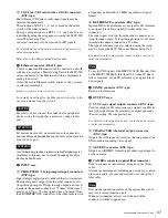
INTERCOM connector (XLR 5-pin)
Connect a headset.
To use a headset with a plug other than an XLR 5-pin plug,
consult a Sony service or sales representative.
HDCU1000 Rear Panel
a
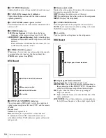
SDI OUTPUT area (BNC-type)
The signal from the video camera may be output as two
HD-SDI or SD-SDI signals.
The signals output from the SDI OUTPUT 3 and SDI
OUTPUT 4 connector can be superimposed character and
marker.
SD-SDI signals are output only when the system is
operating with a field frequency of 59.94/50 Hz.
For details on the field frequency setting, contact a Sony
service or sales representative.
b
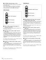
RETURN INPUT area
1
HD-SDI 1 to 4 (HD-SDI return video input 1/2/3/4)
connectors (BNC-type)
Four different HD-SDI return video input signals may be
received independently.
The selection of RET 1, 2, 3, or 4 is made by the return
switch of the video camera.
The type of input signal on RET 1, 2, 3, and 4 may be set
individually using the setup menu, or using the MSU-900
series Master Setup Unit.
For details on the setup menu, contact a Sony service or
sales representative.
Refer also to the Master Setup Unit manual.
2
SD-SDI 1 to 4 (SD component SDI return video
input 1/2/3/4) connectors (BNC-type)
Four different SD component SDI return video input
signals may be received independently when the system is
operating with a field frequency of 59.94/50 Hz.
The selection of RET 1, 2, 3, or 4 is made by the return
switch of the video camera.
The type of input signal on RET 1, 2, 3, and 4 may be set
individually using the setup menu, or using the MSU-900
series Master Setup Unit.
An aspect ratio may also be selected for SD signals.
For details on the setup menu, contact a Sony service or
sales representative.
Refer also to the Master Setup Unit manual.
7
CAMERA connector
qk
AC IN connector
8
Expansion slots
9
INTERCOM/TALLY/PGM connector
2
RETURN INPUT area
4
INPUT area
6
OUTPUT area
0
MIC REMOTE connector
1
SDI OUTPUT area
3
Ethernet connector
qa
WF REMOTE connector
qs
TRUNK LINE connector
qd
I/O PORT connector
qj
MIC1, MIC2 connectors
qh
TRUNK A connector
qg
RCP/CNU connector
qf
WF MODE1, WF MODE2 connectors
5
SPARE connector


