


– 5 –
2.
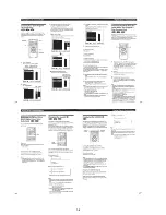
DISK REMOVAL PROCEDURE
(at POWER OFF)
2-1.
How to Open the Door
1) With the top case removed, rotate the gear (D)
1
in direction
A
to open the door. (See Fig. 1)
Fig. 1
2-2. How to Draw out Tray
1) Insert a cross-tip screwdriver into a hole at the bottom, and
rotate the cam gear
2
in direction
B
. (See Fig. 2)
Note:
To prevent a damage of cam gear, rotate it in direction
B
by 1/4 turn.
2) Draw out the tray
3
in direction
C
by hand, and remove a
disk. (See Fig. 2)
Fig. 2
1
Gear (D)
A
B
C
2
Cam gear
3
Tray
Hole
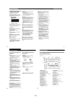
3.
HOW TO SERVICE MB-84 (SIDE B) BOARD
1) Remove the case from the set. (Refer to 2-1)
2) Remove the cover (upper). (Refer to 2-3)
3) Set the MB-84 board as shown in Fig. 3.
Note 1:
Do not disconnect wiring.
Note 2:
Spread a insulating material under the MB-84 board
and through down lest you should short.
4) Mount the extention cable (J-6090-079-A).
(MB-84 (CN601)
↔
FL-107 (CN153))
Fig. 3
MB-84 board
Extention Cable
(J-6090-079-A)
Summary of Contents for DVP-S7700
Page 12: ...1 2 ...
Page 13: ...1 3 ...
Page 14: ...1 4 ...
Page 15: ...1 5 ...
Page 16: ...1 6 ...
Page 17: ...1 7 ...
Page 18: ...1 8 ...
Page 19: ...1 9 ...
Page 20: ...1 10 ...
Page 21: ...1 11 1 11 E ...
Page 36: ...DVP S7700 4 3 4 4 4 1 FRAME SCHEMATIC DIAGRAM 1 2 FRAME 1 2 ...
Page 37: ...DVP S7700 4 5 4 6 FRAME SCHEMATIC DIAGRAM 2 2 FRAME 2 2 ...