


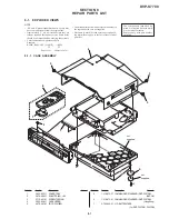


7-2
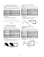
7-2. Adjustment of System Control
1. System Clock 27 MHz Adjustment (MB-84 board)
<Purpose>
27 MHz is the reference clock for the MPEG system, and if it is
not adjusted correctly, checking of 22 MHz and 33 MHz lock in
the following steps will result in NG.
Mode
E-E
Test point
IC206
8
pin
Instrument
Oscilloscope, Frequency counter
Adjusting element
CT201
Specification
27000000 ± 100 Hz
Adjusting method:
1) Confirm that the waveform at TP018 is normal.
2) Adjust CT201 to attain 27000000 ± 100 Hz.
Figure 7-1
7-3. Adjustment of Video System
1. Video Level Adjustment (MB-84 board)
<Purpose>
This adjustment is made to satisfy the NTSC standard, and if not
adjusted correctly, the brightness will be too large or small.
Mode
Video Encoder (IC252) check in test
mode menu “0” Syscon Diagnosis
Signal
Color bars
Test point
LINE OUT (VIDEO) connector
(75
Ω
terminated)
Instrument
Oscilloscope
Adjusting element
RV251
Specification
1 ± 0.02 Vp-p
Adjusting method:
1) In the test mode initial menu “0” Syscon Diagnosis, set so that
Video Encoder (IC252) color bars are generated.
2) Adjust the RV251 to attain 1 ± 0.02 Vp-p.
Figure 7-2
2. S-terminal Output Check (MB-84 board)
<Purpose>
Check S-terminal video output. If it is incorrect, pictures will not
be displayed correctly in spite of connection to the TV with a S-
terminal cable.
Mode
Video Encoder (IC252) check in test
mode menu “0” Syscon Diagnosis
Signal
Color bars
Test point
S VIDEO OUT (S-Y) connector
(75
Ω
terminated)
Instrument
Oscilloscope
Specification
1 ± 0.05 Vp-p
Checking method:
1) In the test mode initial menu “0” Syscon Diagnosis, set so that
Video Encoder (IC252) color bars are generated.
2) Confirm that the S-Y level is 1 ± 0.05 Vp-p.
Figure 7-3
3. Checking Component Video Output B-Y
(MB-84 board)
<Purpose>
This checks component video output B-Y. If it is incorrect, cor-
rect colors will not be displayed when connected to, for instance,
projector.
Mode
Video Encoder (IC252) check in test
mode menu “0” Syscon Diagnosis
Signal
Color bars
Test point
COMPONENT VIDEO OUT (B-Y)
connector (75
Ω
terminated)
Instrument
Oscilloscope
Specification
700 ± 30 mVp-p
Checking method:
1) Confirm that the B-Y level is 700 ± 30 mVp-p.
Figure 7-4
1 ± 0.05 Vp-p
700 ± 30 mVp-p
1 ± 0.02 Vp-p
Summary of Contents for DVP-S7700
Page 12: ...1 2 ...
Page 13: ...1 3 ...
Page 14: ...1 4 ...
Page 15: ...1 5 ...
Page 16: ...1 6 ...
Page 17: ...1 7 ...
Page 18: ...1 8 ...
Page 19: ...1 9 ...
Page 20: ...1 10 ...
Page 21: ...1 11 1 11 E ...
Page 36: ...DVP S7700 4 3 4 4 4 1 FRAME SCHEMATIC DIAGRAM 1 2 FRAME 1 2 ...
Page 37: ...DVP S7700 4 5 4 6 FRAME SCHEMATIC DIAGRAM 2 2 FRAME 2 2 ...