


2-1
Note:
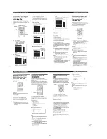
Follow the disassembly procedure in the numerical order given.
2-1. UPPER CASE REMOVAL
2-3. DOOR OPEN/CLOSE MOTOR
REMOVAL
2-2. FRONT PANEL REMOVAL
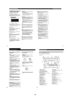
2-4. MB-84 BOARD REMOVAL
SECTION 2
DISASSEMBLY
DVP-S7700
1
Two tapping
screws
4
Upper case
2
Four tapping
screws
3
Two tapping
screws
4
claw
3
Three screws
(B3)
2
Connector
(CN002)
1
Font cable
(CN601)
6
Claw
5
Claw
7
Front panel
1
Flat cable
(CN451)
2
Two screws
(PS3
×
4)
3
Door open/close motor
CN-112 board
1
Two connectors
(CN001, 002)
4
Connector
(CN361)
5
Two screws
(B3)
3
Flat cable
(CN251)
2
Two flat cables
(CN301, 601)
6
Three screws
(B3)
7
Cover (upper)
8
MB-84
board
9
Four flat cables
(CN101, 252, 302, 452)
Summary of Contents for DVP-S7700
Page 12: ...1 2 ...
Page 13: ...1 3 ...
Page 14: ...1 4 ...
Page 15: ...1 5 ...
Page 16: ...1 6 ...
Page 17: ...1 7 ...
Page 18: ...1 8 ...
Page 19: ...1 9 ...
Page 20: ...1 10 ...
Page 21: ...1 11 1 11 E ...
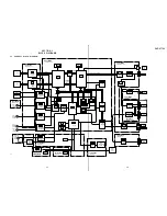
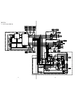
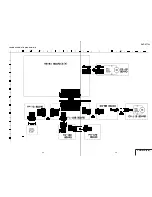
Page 36: ...DVP S7700 4 3 4 4 4 1 FRAME SCHEMATIC DIAGRAM 1 2 FRAME 1 2 ...
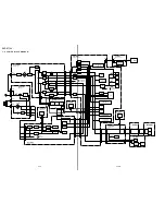
Page 37: ...DVP S7700 4 5 4 6 FRAME SCHEMATIC DIAGRAM 2 2 FRAME 2 2 ...