7-3
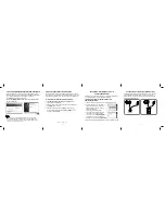
5. 24 MHz Adjustment (MB-80 board)
<Purpose>
24 MHz is the reference clock to generate 36 MHz clock, and if it is
not adjusted correctly, checking of 36 MHz will result in NG.
Mode
E-E
Test point
TP022 (512fs)
Instrument
Oscilloscope, Frequency counter
Adjusting element
CT002
Specification
24576000 ±100Hz
Adjusting method:
1) In the “0” Syscon Diagnosis of the test mode initial menu,
select the DVD mode.
2) Confirm that the waveform at TP022 is normal.
3) Adjust CT002 to attain 24576000 ±100Hz.
7. 36 MHz Lock Check (MB-80 board)
<Purpose>
This checks whether 36 MHz is synchronized with reference clock
27 MHz for MPEG system. If it is not locked, the sounds and pic-
tures are not synchronous during MPEG playing or playing is sus-
pended.
Mode
E-E
Test point
TP021 (PH-COMP)
Instrument
Oscilloscope, Frequency counter
Specification
24.0 ±0.01 kHz
Checking method:
1) In the “0” Syscon Diagnosis of the test mode initial menu,
select the DVD mode.
2) Confirm that a rectangular wave at TP021 is locked.
3) Confirm that the frequency is 24.0 ±0.01 kHz.
Figure 7-5
6. 36 MHz Check (MB-80 board)
<Purpose>
36 MHz is the reference clock for audio system to play DVD, and if
it is not adjusted correctly, no sound will be generated or sounds
will be distorted.
Mode
E-E
Test point
TP020 (36 MHz)
Instrument
Oscilloscope, Frequency counter
Specification
36864000 ±150 Hz
Checking method:
1) In the “0” Syscon Diagnosis of the test mode initial menu,
select the DVD mode.
2) Confirm that the waveform at TP020 is normal.
3) Confirm that the frequency is 36864000 ±150 Hz.
Figure 7-6
Figure 7-7
8. 16 MHz Check (MB-80 board)
<Purpose>
16 MHz is the reference clock for audio system to play CD (includ-
ing video CD), and if it is not adjusted correctly, no sound will be
generated or sounds will be distorted.
Mode
E-E
Test point
IC770 20 pin
Instrument
Oscilloscope, Frequency counter
Specification
16934400 ±75 Hz.
Checking method:
1) Confirm that the waveform at IC770
@º
pin is normal.
2) Confirm that the frequency is 16934400 ±75 Hz.
Figure 7-8
Summary of Contents for DVP-S3000 Operating Instructions / Mode d’emploi
Page 10: ...1 1 SECTION 1 GENERAL This section is extracted from US model instruction manual DVP S3000 ...
Page 11: ...1 2 ...
Page 12: ...1 3 ...
Page 13: ...1 4 ...
Page 14: ...1 5 ...
Page 15: ...1 6 ...
Page 16: ...1 7 ...
Page 17: ...1 8 ...
Page 18: ...1 9 ...
Page 19: ...1 10 ...
Page 20: ...1 11 ...
Page 21: ...1 12 1 12 E ...


