background image

1-12

49

Pl

ay
in

g

 D

is

cs

3

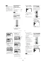
Press 

X

/

x

 to select the item to be 

shuffled.

When playing a DVD VIDEO

DISC*

TITLE

CHAPTER

When playing a VIDEO CD or CD

DISC*

TRACK

When playing a DVD-RW or DATA CD

DISC*

When Program Play is activated

ON

: shuffles titles, chapters, or tracks 

selected in Program Play.

4

Press ENTER.

* You can select “DISC” in All Discs mode only.

To return to normal play

Press CLEAR, or select “OFF” in Step 3.

z

Hints

• You can set Shuffle Play while the player is 

stopped. After selecting the “SHUFFLE” option, 
press 

H

. Shuffle Play starts.

• Up  to  96 chapters in a disc can be played in 

random order when “CHAPTER” is selected.

• You can also select “SHUFFLE” by pressing the 

SHUFFLE button on the player.

Playing repeatedly (Repeat Play) 


You can play all of the titles, albums or tracks 
on a disc or a single title, chapter, album, or 
track repeatedly.
You can use a combination of Shuffle or 
Program Play modes. By selecting All Discs 
mode (page 45), you can repeat all of the 
discs in the player.

1

Press REPEAT during playback.

The following display appears.

2

Press REPEAT repeatedly to select the 
item to be repeated.

When playing a DVD VIDEO

DISC

: repeats all of the titles on the 

current disc in One Disc mode, or all of 
the discs in All Discs mode.

TITLE

: repeats the current title on a 

disc.

CHAPTER

: repeats the current 

chapter.

DISC

continued

50

When playing a DVD-RW

DISC

: repeats all of the titles on the 

selected type in One Disc mode, or all 
of the discs in All Discs mode.

TITLE

: repeats the current title on a 

disc.

CHAPTER

: repeats the current 

chapter.

When playing a VIDEO CD or CD 

DISC

: repeats all of the tracks on the 

current disc in One Disc mode, or all of 
the discs in All Discs mode.

TRACK

: repeats the current track.

When playing a DATA CD (MP3 audio)

DISC

: repeats all of the albums on the 

current disc in One Disc mode, or all of 
the discs in All Discs mode.

ALBUM

: repeats the current album.

TRACK

: repeats the current track.

When Program Play or Shuffle Play is 

activated

ON

: repeats Program Play or Shuffle 

Play.

To return to normal play

Press CLEAR, or select “OFF” in Step 2.

z

Hints

• You can set Repeat Play while the player is 

stopped. After selecting the “REPEAT” option, 
press 

H

. Repeat Play starts.

• You can also select “REPEAT” by pressing the 

REPEAT button on the player.

• You can also select “REPEAT” from the Control 

Menu (page 13).

Repeating a specific portion (A-
B Repeat Play) 


You can play a specific portion of a title, 
chapter or track repeatedly. (This function is 
useful when you want to memorize lyrics, 
etc.)

1

Press DISPLAY twice during playback.

The Control Menu appears.

2

Press 

X

/

x

 to select 

 (A-B 

REPEAT), then press ENTER.

The options for “A-B REPEAT” appear.

SET
OFF

OFF

1 8 ( 3 4 )

1 2 ( 2 7 )

DVD


PLAY

51

Pl

ay
in

g

 D

is

cs

3

Press 

X

/

x

 to select “SET 

t

,” then 

press ENTER.

The “A-B REPEAT” setting display 
appears.

4

During playback, when you find the 
starting point (point A) of the portion to 
be played repeatedly, press ENTER.

The starting point (point A) is set.

5

When you reach the ending point 
(point B), press ENTER again.

The set points are displayed and the 
player starts repeating this specific 
portion.

To return to normal play

Press CLEAR.

To turn off the Control Menu

Press DISPLAY repeatedly until the Control 
Menu is turned off.

Notes

• When you set A-B Repeat Play, the settings for 

Shuffle Play, Repeat Play, and Program Play are 
canceled.

• A-B Repeat Play does not work for titles 

containing still pictures on a DVD-RW in VR 
mode.

• A-B Repeat Play does not work across multiple 

titles (“ORIGINAL” or “PLAY LIST”) on a 
DVD-RW in VR mode.

  Set point A with   

             .

A-B REPEAT

ENTER

A:  18  –   1 : 32 : 55

CHAPTER    TIME   

  Set point B with             .

ENTER

A-B REPEAT

1 8 ( 3 4 )

1 2 ( 2 7 )

DVD

PLAY

A:  18  –   1 : 32 : 55
B:  18  –   1 : 34 : 30

CHAPTER    TIME   

ON

52

Searching for and Managing 
Discs (Disc Explorer)

Displaying the Disc 
Information 


You can search for a disc by checking the 
contents of all the discs loaded in the player 
on the TV screen.

Loading the disc information


Press LOAD when the player is in stop or 
standby mode.

The player reads the disc information of all 
the discs and loads it into memory so that the 
disc type, titles and other text information can 
be displayed.

To cancel loading

Press 

x

.

z

Hint

The player can load the disc information even when 
the power is in standby mode. Press LOAD before 
turning on the player.

Displaying the information of the 
loaded discs

You can look at the loaded disc information 
on the Disc Explorer.
The player has 7 folders (“ALL”, “DVD”, 
“CD”, “A” to “D”) and can display the Disc 
Explorer of each folder.
All the discs in the player are filed in the 
“ALL” folder. At the same time, DVDs are 
automatically filed in the “DVD” folder, and 
CDs, VIDEO CDs, and DATA CDs are filed 
in the “CD” folder. You can file your discs as 
you like in the “A” to “D” folders (page 56).

Press FOLDER.

The Disc Explorer of the “ALL” folder 
appears.

Summary of Contents for DVP-CX875P

Page 1: ... Optical output jack 18 dBm wave length 660 nm DIGITAL OUTPUT COAXIAL Phono jack 0 5 Vp p 75 ohms COMPONENT VIDEO OUTPUT Y PB PR Phono jack Y 1 0 Vp p PB PR interlace 0 648 Vp p progressive 0 7 Vp p 75 ohms VIDEO OUTPUT 1 2 Phono jack 1 0 Vp p 75 ohms S VIDEO OUPUT 1 2 4 pin mini DIN Y 1 0 Vp p C 0 286 Vp p 75 ohms S LINK CONTROL S IN Mini jack General Power requirements 120 V AC 60 Hz Power consu...

Page 2: ...wa SH 63Trd are ex amples of a passive VOM that is suitable Nearly all battery operated digital multimeters that have a 2V AC range are suit able See Fig A 1 Check the area of your repair for unsoldered or poorly sol dered connections Check the entire board surface for solder splashes and bridges 2 Check the interboard wiring to ensure that no wires are pinched or contact high wattage resistors 3 ...

Page 3: ...D FLASH I F EXTENSION I O Schematic Diagram 4 31 AI 25 Printed Wiring Board 4 33 AI 25 LOADING TURN TABLE DOOR MOTOR DRIVE INTERFACE Schematic Diagram 4 35 VD 33 Printed Wiring Board 4 37 VD 33 VIDEO BUFFER Schematic Diagram 4 39 AV 66 Printed Wiring Board 4 41 AV 66 AUDIO AMP Schematic Diagram 4 43 FR 189 Printed Wiring Board 4 45 FR 189 INTERFACE CONTROL Schematic Diagram 4 47 CK 118 Printed Wir...

Page 4: ...tment Related Parts Arrangement 7 6 8 REPAIR PARTS LIST 8 1 Exploded Views 8 1 8 1 1 Case Assembly 8 1 8 1 2 Front Panel Assembly 1 8 2 8 1 3 Front Panel Assembly 2 8 3 8 1 4 Chassis Assembly 1 8 4 8 1 5 Chassis Assembly 2 8 5 8 1 6 Chassis Assembly 3 8 6 8 1 7 Mechanism Deck Assembly 1 8 7 8 1 8 Mechanism Deck Assembly 2 8 8 8 2 Electrical Parts List 8 9 ...

Page 5: ...se Page 2 1 Power Block Page 2 1 Optical Pick Up Page 2 3 VD 33 Board Page 2 2 AV 66 Board Page 2 2 AI 25 Board Page 2 3 MB 107 board Page 2 2 T Driving Block Page 2 2 Mechanical Deck Assembly Page 2 1 Mechanical Deck Block Page 2 3 Center Guide Assembly Page 2 3 Front Panel Block Removal Page 2 1 ...

Page 6: ... 6 2 CONNECTION OF MB 107 BOARD JIG J 6090 125 A 29 pin FFC 400 mm for MB 107 SIDE B AI 25 MB 107 AV 66 VD 33 ...

Page 7: ...lly susceptible to this 7 Example of discs that the player cannot play The player cannot play the following discs All CD ROMs including PHOTO CDs CD Rs CD RWs other than those recorded in the following formats music CD format video CD format MP3 format that conforms to ISO9660 Level 1 Level 2 or its extended format Joliet Data part of CD Extras DVD ROMs DVD Audio discs HD layer on Super Audio CDs ...

Page 8: ... Current scene 68 Lights up when the player outputs progressive signals 91 Playing time 68 Disc type Current track CD VIDEO CD or album DATA CD 68 Lights up when playing MP3 audio tracks 43 Playing status Current disc Current play mode 45 All discs mode 45 Lights up when the player outputs progressive signals 91 Current index CD VIDEO CD or track DATA CD 68 11 Rear panel A AUDIO OUTPUT L R 1 2 jac...

Page 9: ...dio setting SUBTITLE page 75 Displays the subtitles Changes the subtitle language ANGLE page 74 Changes the angle TVS page 72 Selects the surround functions ADVANCED page 69 Displays the information bit rate or layer of the disc currently playing PARENTAL CONTROL page 80 Set to prohibit playback on this player 15 z Hint The Control Menu icon indicator lights up in green when you select any item ex...

Page 10: ...ogressive signals Hook up your TV using pattern C on page 21 and then run Quick Setup on page 29 z Hint When connecting to a monaural TV use a stereo mono conversion cord not supplied Connect the VIDEO OUTPUT jack on the player to the TV s video input jack and connect the AUDIO OUTPUT L R 1 2 jacks to the TV s audio input jack 1 Audio video cord supplied 2 Power source CD DVD Player to video input...

Page 11: ...or video component has an S LINK CONTROL S connector You can control the player by pointing the remote at the remote sensor on the TV or video component This feature is convenient when you placed the player and the TV or video component away from each other Connect the TV or video component via the S LINK CONTROL S jack using the S link control S cord not supplied Refer to the instructions supplie...

Page 12: ...ing to an AV amplifier receiver having a Dolby Surround Pro Logic decoder and 3 to 6 speakers You can enjoy the Dolby Surround effects only when playing Dolby Surround audio or multi channel audio Dolby Digital discs If your amplifier receiver has L and R audio input jacks only use If your amplifier receiver has a digital input jack use Note When connecting 6 speakers replace the monaural rear spe...

Page 13: ...type of jack you are using AUDIO OUTPUT L R DIGITAL OUTPUT A D A B 1 C 1 B 2 C 2 D B D AUDIO SETUP AUDIO ATT AUDIO DRC DIGITAL OUT DOLBY DIGITAL DTS OFF STANDARD ON DOWNMIX DOLBY SURROUND DOLBY DIGITAL D PCM D PCM B 2 C 2 D AUDIO SETUP AUDIO ATT AUDIO DRC DIGITAL OUT DOLBY DIGITAL DTS OFF STANDARD ON DOWNMIX DOLBY SURROUND OFF ON OFF D PCM 31 Hookups 14Press X x to select whether or not you wish t...

Page 14: ...ital jack of the player Set the sound to STEREO using the AUDIO button when you play DTS sound tracks on a CD page 71 Do not play DTS sound tracks without first connecting the player to an audio component having a built in DTS decoder The player outputs the DTS signal via the DIGITAL OUTPUT COAXIAL or OPTICAL jack even if DTS in AUDIO SETUP is set to OFF in the Setup Display page 95 and may affect...

Page 15: ...OW2 Slow playback direction slower than SLOW1 Y PAUSEX Pause Y SLOW2 Slow opposite direction slower than SLOW1 DVD only Y SLOW1 Slow opposite direction DVD only To return to continuous play Press H To manually play the disc frame by frame using the click shuttle Jog mode 1 Press JOG The player enters the pause mode 2 Turn the click shuttle Depending on the turning speed playback goes to frame by f...

Page 16: ... z Hint You also can display the lists with the MENU button on the player Notes On playback This player can play MP3 audio tracks recorded in the following sampling frequencies 32 kHz 44 1 kHz 48 kHz The player cannot play audio tracks in MP3PRO format If you put the extension MP3 to data not in MP3 format the player cannot recognize the data properly and will generate a loud noise which could dam...

Page 17: ...chapter or track you want to program When playing a DVD VIDEO For example select chapter 03 of title 02 Press X x or the number buttons to select 02 under T then press ENTER Next press X x or the number buttons to select 03 under C then press ENTER When playing a VIDEO CD or CD For example select track 04 Press X x or the number buttons to select 04 under T then press ENTER 7 To program other disc...

Page 18: ...t REPEAT from the Control Menu page 13 Repeating a specific portion A B Repeat Play You can play a specific portion of a title chapter or track repeatedly This function is useful when you want to memorize lyrics etc 1 Press DISPLAY twice during playback The Control Menu appears 2 Press X x to select A B REPEAT then press ENTER The options for A B REPEAT appear SET OFF OFF 1 8 3 4 1 2 2 7 DVD PLAY ...

Page 19: ... information again by pressing LOAD or place a new disc in the same slot and play it ALL DVD CD A B C D 1 Super Car Chase Skiing the World Music Madness 2 3 4 5 Action DVD CD Action DVD CD VIDEO CD Disc slot number EZ Easy Play slot Current folder is highlighted Disc type Current disc Text information DVD text CD text Disc Memo Jacket picture Genre 55 Searching for and Managing Discs Disc Explorer...

Page 20: ...cted a folder 3 Select a character by pressing C X x c The selected character changes color 4 Press ENTER The selected character is input 5 Repeat Steps 3 and 4 to input other characters 6 When you have entered all the characters for the Disc Memo or folder name press EDIT The DISC MEMO INPUT display or the FOLDER NAME INPUT display disappears and the Disc Memo or folder name is stored To cancel t...

Page 21: ...CD Select the sorting item from among here Sorting item indicator position when you sort by genre SORT ALL DVD CD A B C D 1 Super Car Chase MONACO Highway Touring Music Madness 3 198 2 4 Action DVD Action DVD CD CD Skiing the World Action DVD BRAHMS SYMPHONY4 Classical SORT 63 Searching for a Scene Searching for a Scene Searching for a Title Chapter Track Index Scene You can search a DVD by title ...

Page 22: ...ctions You can also start playback from the selected angle After performing Step 3 of Searching by Scene page 64 select the angle using C X x c and press ENTER 67 Viewing Information About the Disc Viewing Information About the Disc Checking the Playing Time and Remaining Time You can check the playing time and remaining time of the current title chapter or track Also you can check the DVD CD text...

Page 23: ...xample when playing a disc containing a song with the vocals on the right channel and the instruments on the left channel you can hear the instruments from both speakers by selecting the left channel 1 Press AUDIO during playback The following display appears 2 Press AUDIO repeatedly to select the desired audio signal When playing a DVD VIDEO Depending on the DVD VIDEO the choice of language varie...

Page 24: ...back The number of the angle appears on the display 2 Press ANGLE repeatedly to select the angle number The scene changes to the selected angle z Hints You can display all the angles recorded on the disc on the same screen and start playback directly from the chosen angle The angles are displayed on a screen divided into 9 sections For details see page 64 You can also select ANGLE from the Control...

Page 25: ... the picture appear clear and crisp by enhancing the outlines of images on your TV screen Also this function can soften the images on the screen 1 Press DISPLAY twice during playback The Control Menu appears 2 Press X x to select DIGITAL VIDEO ENHANCER then press ENTER The options for DIGITAL VIDEO ENHANCER appear C 0 1 3 2 5 5 PICTURE BRIGHTNESS COLOR HUE RESET 1 3 3 1 RETURN 1 8 3 4 1 2 2 7 DVD ...

Page 26: ...FF STANDARD 8 7 6 5 NC17 R PARENTAL CONTROL LEVEL STANDARD USA 4 PG13 83 Using Various Additional Functions To play a disc for which Parental Control is set 1 Select the disc and press H The display for entering your password appears 2 Enter your 4 digit password using the number buttons then press ENTER The player starts playback z Hint If you forget your password press OPEN CLOSE to open the fro...

Page 27: ...tions Controlling the volume of your AV amplifier receiver with the remote 1 Slide the TV DISC EXPLORER DVD switch to DVD 2 Hold down 1 and enter your AV amplifier receiver s manufacturer s code see the table below using the number buttons 3 Release 1 The VOL buttons control the AV amplifier s volume If you want to control the TV volume Slide the TV DISC EXPLORER DVD switch to TV Code numbers of c...

Page 28: ...ored in memory Note If you operate the player while the picture is being stored in memory the player will fail to store the picture COMPONENT OUT This will change the type of signal output from the COMPONENT VIDEO OUTPUT jacks on the player See page 100 for more information about the different types z Hint When the player outputs progressive signals the PROGRESSIVE indicator lights up Note If you ...

Page 29: ... signal DOLBY SUR ROUND Select this when the player is connected to an audio component that conforms to Dolby Surround Pro Logic NORMAL Select this when the player is connected to an audio component that does not conform to Dolby Surround Pro Logic ON Normally select this position When you select ON see Setting the digital output signal for further settings OFF The influence of the digital circuit...

Page 30: ...ossible problems press H E XX xx is a number To prevent a malfunction the player has performed the self diagnosis function Contact your nearest Sony dealer or local authorized Sony service facility and give the 5 character service number Example E 61 10 99 Additional Information Glossary Chapter page 10 14 63 Sections of a picture or a music feature that are smaller than titles A title is composed...

Page 31: ...h 1283 Javanese 1287 Georgian 1297 Kazakh 1298 Greenlandic 1299 Cambodian 1300 Kannada 1301 Korean 1305 Kashmiri 1307 Kurdish 1311 Kirghiz 1313 Latin 1326 Lingala 1327 Laothian 1332 Lithuanian 1334 Latvian Lettish 1345 Malagasy 1347 Maori 1349 Macedonian 1350 Malayalam 1352 Mongolian 1353 Moldavian 1356 Marathi 1357 Malay 1358 Maltese 1363 Burmese 1365 Nauru 1369 Nepali 1376 Dutch 1379 Norwegian 1...

Page 32: ...3 6 3 Two screws BV3 10 5 Front panel block 1 Flexible flat cable CN307 2 Flexible flat cable CN103 1 Screw BV3 10 2 Two screws BV3 10 6 Connector CN201 7 Two screws BV3 8 8 Power block 4 5 3 Two screws BV3 10 7 Mechanical deck assembly 4 Four screws BV3 6 6 Screw BV3 6 5 Two screws BV3 10 1 Flexible flat cable CN003 2 Flexible flatcable CN203 3 Flexible flat cable CN204 Note After installing the ...

Page 33: ...e CN201 3 Three screws BV3 10 2 Connector CN202 4 VD 33 board 3 Five screws BV3 10 2 Connector CN101 1 Flexible flat cable CN103 3 Flexible flat cable CN601 2 Flexible flat cable CN501 4 Connector CN101 1 Flexible flat cable CN103 5 Six screws BV3 8 6 MB 107 board 2 Three screws cushion stopper 1 Flexible flat cable CN101 3 T Driving block ...

Page 34: ...AL 2 AI 25 board 1 Four screws BVTP3 8 2 Screw BV3 6 3 Chuck driving link 1 Two flexible flat cables CN002 CN004 4 Three screws BV3 10 5 Center guide assembly 1 Two screws BV3 10 CN001 CN002 2 Mechanism deck block 1Slider U 6Insulator BR 8Optical pick up 4Three step screws M 3Two flexible flat cables 7Two insulators BR 2 5 ...

Page 35: ...AV 66 AUDIO AMP FR 189 INTERFACE CONTROL CK 118 DISC SENSOR CS 58 CHUCKING SENSOR LC 78 LOADING CHUCKING MOTOR LS 62 LOADING SENSOR LL 12 LOADING GUIDE INDICATOR L LR 17 LOADING GUIDE INDICATOR L FL 128 FUNCTION SWITCH SW 374 EJECT SWITCH TS 154 TURN TABLE SENSOR TM 129 TURN TABLE MOTOR DA 32 DOOR SENSOR DM 105 DOOR MOTOR ZSSR113M SWITCHING REGULATOR ...

Page 36: ... LINK SW 5V SW 10V SWITCHING REG SW 5V 1 8V SW 3 3V M 11V REG 10V SW SW 5V CK 118 BOARD SEE PAGE 4 51 LS 62 BOARD SEE PAGE 4 51 CS 58 BOARD SEE PAGE 4 52 PH221 222 LOADING SENSOR 1 2 PH261 262 CHUCKING SENSOR 1 2 LL 12 BOARD SEE PAGE 4 52 D241 D281 LR 17 BOARD SEE PAGE 4 52 M M M131 TURN TABLE MOTOR M M M201 LOADING MOTOR M M M202 CHUCKING MOTOR LC 78 BOARD SEE PAGE 4 51 TS 154 BOARD SEE PAGE 4 59...

Page 37: ... VCI 19 39 20 22 16 17 155 GIO2 INT4 05 1 2 RF A D E H VC PD DVD LD 26 Q202 CD LD DRIVE CD LD CD LD VR SLA SLB SPM INLIM TRK 127 ADC3 FCS PS TSD M 40 42 43 VREF 3 3V LDON 159 161 162 167 GIO6 SDI GIO7 SDO GIO8 SCK GIO13 XSDPIT XSDPCS XRST XDRVMUTE SIGO XLDON FE TE PI SSDFCTI SS MON MDSO MDPO SPMUTE SLDA SLDB LMP LMM TSD LMCTL TDRV FDRV SPFG SLE 24 25 17 16 22 20 13 8 6 12 4 3 15 23 18 26 2 1 CN001...

Page 38: ...DQMU CS WE CAS RAS WE RAS LCAS UCAS AUDIO SEE PAGE 3 11 ACH12O LRCKO BCKO ACH12 LRCK BCK H DATA 0 15 HAD 0 21 HA 0 21 HD 0 15 D 0 7 A 0 7 HA 0 7 HD 8 15 XRD XWRH RSTn DM ACK1In DM RQ1On DM ACK0In DM RQ0On ACLK HAD23I HAD22I CLKI SCLKIN 200 199 HWAIT0n HIRQ0n HA 0 21 HD 0 15 HD 0 15 XRST 512FSAVD 33MARP XWRH XRD XFRRST XARPIT XARPCS XWAIT XAVDCS2 XAVDCS3 27MAVD XAVDIT DREQ0 DACK0 DREQ1 DACK1 XWR XR...

Page 39: ...0 SIGNAL PROCESSOR SEE PAGE 3 5 RF SERVO SEE PAGE 3 4 05 512FSAVD X102 27MHz FSEL 512FS2CH 33MARP 29 SO1 SO1 30 SC1 SC1 79 XDACS XDACS INT1 CS4X XWAIT 35 XRST XRST XRST XRD XWRH XWRL 512 2OUT 4 27 2OUT 15 33 1OUT 512 1OUT XTI XTO 27MAVD X1 X2 HD 0 15 HA 0 21 XRD XWRH XRD XWRH XRD XWRH 7 CN103 1 2 3 4 2 5 6 WP SCL SDA 59 6 CS SCL SDA WP AN3 CS1X 84 17 WE 41 40 39 OE UB LB XSRWE WIDE WIDE SI0 SO0 SC...

Page 40: ...4 WE 100 RAS 102 CAS VIDEO LEVEL CN601 PO 0 7 16M SDRAM COMP OUT RV602 3 8 6 29 33 31 7 IC102 VIDEO BUFFER 12 15 17 24 22 20 9 3 15 13 11 7 1 5 VD 33 BOARD SEE PAGE 4 39 CN103 CN101 V_MUTE INTERFACE CONTROL SEE PAGE 3 15 J102 J103 1 2 PB COMPONENT VIDEO OUT Y PR 16 LINE OUT VIDEO 1 VIDEO 2 Y C Y C S VIDEO OUT VIDEO IN Y IN C IN MUTE1 Y IN Cb IN Cr IN MUTE2 VIDEO OUT Y OUT C OUT Y OUT Cb OUT Cr OUT...

Page 41: ...S 512FS2CH MA_MUTE D501 CN501 SPDIF1 5 6 3 2 IC202 AUDIO AMP CN201 INTERFACE CONTROL SEE PAGE 3 15 J202 AV 66 BOARD SEE PAGE 4 43 IC203 OPTICAL DIGITAL OUT COAXIAL J201 A_MUTE CN202 1 D IN 7 1 Q202 206 208 MUTE DRIVE L R AUDIO 1 LINE OUT AUDIO 2 R L 3 11 7 5 8 9 2 MUTE V POWER 2 SEE PAGE 3 19 Q210 MUTE Q211 MUTE Q212 BUFFER IC503 4 IC503 2 IC503 1 DVD 4 3 Vp p 48 1 kHz CD 4 3 Vp p 44 1 kHz DVD 3 3...

Page 42: ...M DSPW LM LM CM CM DM DM TSW2 TSW3 DRSW1 DRSW2 Q308 8 10 TM 5 CN103 2 2 CN309 CN305 1 2 CN308 TM 12 10 8 2 7 9 5 6 13 15 14 3 1 11 7 6 8 4 2 11 CN003 CN101 Q004 INVERTER Q003 DISC SENSOR Q002 INVERTER TURN TABLE SENSOR 1 PH001 Q001 1 2 7 8 6 CN221 1 2 7 8 6 CN001 LDSW1 LDSW2 CKSW1 CKSW2 LT 1 3 4 2 AI 25 BOARD 1 2 SEE PAGE 4 35 CK 118 BOARD SEE PAGE 4 51 LS 62 BOARD SEE PAGE 4 51 LOADING SENSOR 1 P...

Page 43: ...6 5 4 3 1 JOG_CW JOG_CCW AD4 AD3 AD5 ACS_CW ACS_CCW AD7 AD6 AD2 L_JOG L_DCHG L_EASY L_DSRC L_LOAD L_FLIP 33 AD3 31 AD2 35 AD6 36 AD7 28 ACS_CCW 29 ACS_CW 34 AD5 S104 PICTURE MODE SURROUND S106 5 4 10 9 13 14 15 16 18 FLIP S410 S411 DISC CHANGE TOP MENU S401 12 1 3 7 6 8 2 S412 DIRECT SEARCH DISPLAY S402 MENU S403 S404 S414 S415 S416 JOG S417 LOAD S405 REPEAT S406 TIME TEXT S407 SHUFFLE S408 S409 S...

Page 44: ...5V 5 CN101 5 CN103 TS 154 BOARD SEE PAGE 4 59 PH001 PH101 TURN TABLE SENSOR 2 3 4 CN221 2 CN222 LS 62 BOARD SEE PAGE 4 51 PH221 SW 5V SW 5V LOADING SENSOR 1 PH222 LOADING SENSOR 2 4 CN223 2 CN261 2 CN262 CS 58 BOARD SEE PAGE 4 52 PH261 CHUCKING SENSOR 1 PH262 CHUCKING SENSOR 2 2 CN241 LL 12 BOARD SEE PAGE 4 52 D241 4 CN281 LR 17 BOARD SEE PAGE 4 52 D281 3 CN161 DA 32 BOARD SEE PAGE 4 60 DOOR SENSO...

Page 45: ...FL403 FILTER FL402 IC103 PLL IC101 EEPROM IC604 VIDEO ENCORDER IC603 16M SDRAM IC702 64M NAND FLASH IC602 I P CONVERTER IC104 SYSTEM CONTROL FILTER FL102 IC108 1M SRAM FILTER FL109 FILTER FL106 IC106 32M FLASH IC107 OTP FILTER FL105 or IC701 NAND FLASH I F EXTENSION I O FILTER FL701 POWER 1 SEE PAGE 3 18 AV 66 BOARD SEE PAGE 4 43 IC201 5V REG 1 OUT 3 IN MUTE V SW 10V EVER 5V EVER 11V D201 IC203 OP...

Page 46: ...resistors have characteristic curve B unless otherwise noted 2 nonflammable resistor 5 fusible resistor C panel designation f internal component C adjustment for repair U B Line V B Line Circled numbers refer to waveforms Voltages are dc between measurement point Readings are taken with a color bar signal on DVD refer ence disc and when playing CD reference disc Readings are taken with a digital m...

Page 47: ...D 3 3V GND Cr R GND WIDE GND Cb B Y G GND IPSW GND V GND GND SC SY AC_IN L AC_IN N GND G RF N C H FCS PD C GND B TRK CD LD N C VR D VC A LD GND TRK N C MOD E VCC F DVD LD FCS SW N C SLB SPM LED SLB GND SLA INLIM SLA SPM TRK MOD PD VR LD GND GND FCS VC C SW D G E A RF B N C F GND TRK N C H FCS DVD LD CD LD VCC SLA SLB LED SPM SPM SLB INLIM GND SLA M_GND SW 3 3V M 11V GND M 11V SW 5V GND M_GND 1 8V ...

Page 48: ...ND DIMM DSENS GND LDSW2 CKSW2 TSW1 CKSW1 CM SW 5V SW 5V GND GND CKSW2 LT LDSW2 CKSW1 LDSW1 CM LM LM CM CKSW1 LTR SW 5V GND CKSW2 LTR SW 5V N C DRSW1 DRSW2 SW 5V GND GND SW 5V DRSW2 DRSW1 L_DCHG AD2 L_DSRC AD7 LED 5V L_LOAD ACS_CW AD6 JOG_CCW GND L_FLIP L_JOG AD5 JOG_CW AD3 ACS_CCW AD4 L_EASY GND AD5 GND RIGHT GND UP ENTER JOG_CCW LEFT COMMON JOG_CW DOWN GND GND AN4 LM LM CM CM N C SW 5V LTL N C SW...

Page 49: ...VO SPEED AND PHASE VIDEO SIGNAL FOCUS SERVO SIGNAL Y CHROMA TRACKING SERVO DVD CD CDV MB 107 BOARD 1 10 CN203 204 SEE PAGE 4 9 D E 3 1 2 F TK 63 BOARD 4 C B 6 05 A G 5 4 2 PRINTED WIRING BOARDS AND SCHEMATIC DIAGRAMS TK 63 RELAY PRINTED WIRING BOARD AND SCHEMATIC DIAGRAM Ref No TK 63 board 2 000 series There are a few cases that the part isn t mounted in this model is printed on this diagram CN001...

Page 50: ...625 C261 C262 CL628 CL629 CL631 CL633 CL637 CL638 CL639 CL640 C309 CL641 R964 CL644 CL646 CL647 CL648 CL649 CL650 CL651 CL652 CL653 CL654 CL655 C626 C635 C604 C607 C609 C610 C611 C619 16 17 32 33 48 49 1 64 IC604 RV601 RV602 1 2 22 23 CN601 1 25 26 50 IC603 R422 R424 R425 R429 R430 R433 C429 C431 C432 C433 C434 C435 C436 R402 C401 C405 C124 C127 45 89 132 44 88 133 1 176 IC301 FB110 FB111 C125 R10...

Page 51: ...614 C515 C516 C615 C519 C520 C523 JL226 JL227 JL228 C530 C536 C616 R822 C617 C618 PC00767 PC00768 PC00769 PC00770 PC00771 JL229 JL230 JL142 JL231 JL144 JL232 JL146 JL141 JL233 JL143 JL147 JL234 JL145 PC00790 C637 C638 C639 5 4 3 2 1 IC601 5 4 3 2 1 IC605 C801 C802 C803 JL235 C805 C806 C807 C809 C811 C813 C901 C902 C904 C905 C906 C907 C908 C909 C912 C929 C932 C934 C935 C936 C937 C201 PC00860 PC0086...

Page 52: ...L225 JL226 JL227 JL230 JL228 JL229 JL231 JL232 JL233 JL234 JL235 E SLA CD_LD PI SLB TE FE SSCK SSWD SSRD PI TZC E F SSRD A TE TZC MIRR SLB SLB SLA TRK FCS TRK INLIM FCS SPM SPM SLA CDPD N C DVDPD RFIN MEVO CDLD MIRR VPA DVD LD RF TZIN F GND E MB SLA MEV AIP RFIP DIP FE D LDON TPA ATON BYP2 VCC LD GND F INLIM A SLB C2 MIN G MON AIN SLB LDSELO TE D SRD C SCLK PI RX PII BYP A GND N C FCS GND E H D2 W...

Page 53: ... 44 45 46 11 15 36 40 24 25 47 48 49 50 IC302 TK11133CSCL G 1 2 3 4 5 TCK TMS XFRRST TDIKT RAMD15 RAMD13 RAMD14 RAMD10 RAMD9 RAMD11 RAMD12 RAMD8 RAMD6 RAMD5 RAMD4 RAMD3 RAMD2 RAMD1 RAMD7 RAMD0 RAMA9 RAMA8 RAMA7 RAMA6 RAMA5 RAMA4 RAMA3 RAMA2 RAMA1 RAMA0 SDEF XSAK XSHD SDCK CDDOUT SDI0 SDI1 SDI2 SDI3 SDI4 SDI5 SDI6 SDI7 TESTK3 GND GND GND FDRV FDRV TDRV TDRV FDRV FDRV TDRV TDRV RAMD0 RAMD1 RAMD2 RAM...

Page 54: ...5I DO ACH56O IVALIn HAD18I IOVSS07 DVO4 TDI CVD01 DVSS33 HAD22I SDRASOn COUT SDCS1On IOVDD12 IOVSS01 CVD06 TRST CDBCKI SDAD5O TCK MBIST_EN BF_ID HAD5I DMACK1In IOVDD00 SDDQ0 HAD3I HCPUMDI ICLKI HRWn DT0I HAD7I SDDQM1O SDCS0On YOUT HSYNCOn I2C_DATA SDDQ13 HAD15I DVO1 IOVSS03 ROUT IOVDD09 IOVDD10 DT4I ACH12O BCKO ACH34O ISTARTIn HAD19I SDDQ8 DVDD33 HAD23I AVSS02 HAD8I CDIN1I CVS01 SDDQ10 CVS05 SDAD2...

Page 55: ...CL204 CL205 FCS FCS TRK TRK SLB SLB SLA SLA SPM SPM FAN8034L IC202 1 2 3 4 5 6 14 15 16 17 18 19 20 21 22 23 24 27 28 29 30 31 32 33 34 35 36 40 41 42 43 44 45 46 47 48 50 51 52 49 13 25 26 37 38 39 11 12 9 10 7 8 SPM LDM SPM SLA SLB SLB SLA FCS TRK TRK SLB SLB SPM SPM FCS FCS TRK TRK SLA SLA LDM FCS FWD OUT5 DO5 DO4 REV CTL DO3 IN5 DO5 DO6 MUTE34 PVCC2 DO6 MUTE5 PGND2 MUTE12 SGND DO4 TSD M MB 107...

Page 56: ... SI2 HAI2 HAI3 HAI4 HAI1 HAI5 HAI9 HAI6 HAI8 HAI7 HAI12 HAI10 HAI11 HAI14 HAI16 HAI13 HAI15 HAI20 HDI6 HDI1 HAI17 HAI9 HAI20 HDI2 HAI9 HAI10 HDI9 HAI18 HAI2 HDI10 HAI11 HAI3 HAI12 HAI1 HDI3 HAI13 HAI0 HAI17 HAI19 HAI5 HAI4 HAI20 HDI7 HDI11 HDI8 HAI21 SI2 HAI15 HAI19 HAI3 HAI14 SO0 HAI18 HAI6 HAI5 HDI3 HDI12 SC0 HAI17 HDI4 HAI16 HAI13 HAI16 HAI6 HDI15 SO2 HAI4 HAI7 HDI7 HAI19 HDI15 HDI6 HAI1 HDI9 H...

Page 57: ..._GND M_GND M 11V 27 2OUT SW 3 3V M 11V 27 1OUT 29P CN103 1 2 3 4 5 6 7 8 9 10 11 12 13 14 15 IFBSY LDMM LDMM DIMM DIMM DSADJ DSADJ DRMP DRMP DRMM DRMM XFRRST GND SC0 CM LDM SO0 SI0 TRMM TRMM XIFCS 20 22 21 23 24 25 26 27 28 29 19 18 17 16 TSCTL TSCTL DRSW1 DRSW1 CKSW1 CKSW1 TSW1 TSENS TSW2 TSW2 TSW3 TSW3 CM LDM DSENS DSENS 3 3V_MNT LDMP LDMP CKSW2 CKSW2 LDSW2 LDSW2 TRMP TRMP DRSW2 DRSW2 LDSW1 LDMM...

Page 58: ... 64 65 66 67 68 69 70 71 72 73 74 75 76 77 78 79 80 81 82 83 84 85 86 87 88 89 90 91 92 93 94 95 96 97 98 99 100 101 102 103 104 105 106 107 108 109 110 111 112 113 114 115 116 117 118 119 120 121 122 123 124 125 126 127 128 129 130 131 132 133 134 135 136 137 138 139 140 141 142 143 144 1 2 3 4 5 A1 DQ10 A2 DQ11 A3 DQ12 A9 DQ7 DQ6 DQ5 DQ4 DQ3 DQ2 DQ13 A8 DQ14 A7 A6 DQ15 A5 A4 DQ1 DQ0 A10 DQ8 A0 D...

Page 59: ... 14 15 1 2 3 4 5 SDA SCL SDA SCL JL615 JL614 JL613 JL612 CBCR3 CBCR4 CBCR0 CBCR1 CBCR2 CBCR5 CBCR6 CBCR7 CBCR8 CBCR9 Y8 Y9 Y0 Y1 Y2 Y3 Y4 Y5 Y6 Y7 PO7 PO6 PO5 PO4 PO3 PO2 PO1 PO0 DAC C RSET2 P_HSYNC P_Y 9 EXT_LF DAC A P_C 0 GND S_BLANK P_C 2 S 2 RESETB GND_IO S 4 P_C 5 SCLK COMP2 S 8 S 0 P_Y 8 P_Y 2 SCANEN P_Y 6 P_C 8 P_C 3 P_Y 0 VREF CLKIN DAC E P_Y 3 TESTMODE P_Y 4 DAC D P_VSYNC P_Y 7 SPI_12C_EN...

Page 60: ... P_GND CSN VDD DZFL SDTI LRCK DSDM VSS AOUTL AOUTR PDN CCLK DCLK AOUTR DZFR MCLK BICK CDTI DSDR DSDL AOUTL A 5V ALT A 5V ALT N C ART ART SPDIF GND GND N C IC503 AUDIO D A CONVERTER D 8 10 E H 3 1 11 2 F I MB 107 BOARD 9 10 4 C B 7 6 05 9 A 12 G 5 SIGNAL SIGNAL PATH PB AUDIO MB 107 BOARD 5 10 MB 107 BOARD 3 10 MB 107 BOARD 5 10 MB 107 BOARD 3 10 MB 107 BOARD 6 10 MB 1057BOARD 6 10 CN201 SEE PAGE 4 ...

Page 61: ...k R730 1k R732 1k R735 HD15 HA0 HA1 HA2 HA3 HA4 HA19 HD8 HD9 HD10 HD11 HD12 HD13 HD14 HD8 HD9 HD10 HD11 HD15 HD14 HD13 HD12 NFWP NFWE NFALE NFCLE NFTEST NFRE NFCE NFBSY TSCTL DSADJ DRSW1 LDSW2 DRSW2 CKSW2 CKSW1 DSENS DIMM HA19 HA4 HA3 HA2 HA1 HA0 HD15 HD14 HD13 HD12 HD11 HD10 HD9 HD8 NFBSY NFCE NFCLE NFALE NFWP NFRE NFWE NFTEST DIMM DRMM DRMP LDMM LDMP TRMP TRMM TSW2 LDSW1 TSW3 TRMP TRMM DRMP DRMM...

Page 62: ...5 JL316 JL317 JL318 JL319 JL320 JL321 JL322 JL323 JL324 JL325 JL326 JL327 JL328 JL329 JL330 JL331 JL332 JL333 JL334 JL335 JL336 JL337 JL338 JL339 JL340 JL341 JL342 JL343 JL344 JL345 JL346 JL347 JL348 JL349 JL350 JL351 JL352 JL353 JL354 JL355 JL356 JL357 JL358 JL359 JL360 JL361 JL362 JL363 JL364 JL365 JL366 JL367 JL368 JL369 JL370 JL371 JL372 JL373 JL374 JL375 JL376 JL377 JL378 JL379 JL380 JL381 JL...

Page 63: ...2 13 14 15 16 17 18 19 20 21 22 23 24 25 26 27 28 29 7P CN302 1 2 3 4 5 6 7 7P CN304 1 2 3 4 5 6 7 0 60mm JS301 0 60mm JS302 0 60mm JS303 0 60mm JS304 0 60mm JS306 0 60mm JS305 0 60mm JS307 0 60mm JS309 0 60mm JS308 0 60mm JS310 0 1u C322 0 1u C323 DRMP DRMM DM DM TM LM TRMM LDMM TM LM TRMP LDMP LM LM DM DM TM TM LDMP LDMM DRMP DRMM TRMP TRMM SC0 3 3V_MNT XFRRST XIFBUSY XIFCS SI0 SO0 3 3V_MNT 3 3V...

Page 64: ...8 JL129 JL130 JL131 JL132 JL133 JL134 JL135 JL136 JL137 JL156 JL157 JL158 JR101 JR102 JR103 C B E Q105 C B E Q106 C B E Q107 R108 R109 R110 R111 R112 R113 R114 R115 R116 R117 R118 R119 R120 R121 R122 R123 R124 R125 R126 R127 R128 R129 R130 R132 R133 R134 R135 R136 R137 VD 33 BOARD A B C D E F G 1 2 3 4 5 6 7 8 9 10 11 12 13 05 VIDEO OUTPUT 1 2 S VIDEO OUTPUT 1 2 1 2 3 4 2 6 8 7 9 5 3 1 10 14 15 2 ...

Page 65: ...TX Q105 UN2111 TX Q106 UN2111 TX Q107 FB101 FB102 15P CN103 1 2 3 4 5 6 7 8 9 10 11 12 13 14 15 2P J101 1 1V 3 GND 2 2V 3P J102 1 R Y 2 RYGND 3 B Y 4 BYGND 5 Y 6 YGND 7P CN101 1 2 3 4 5 6 7 16V 47u C103 LND101 CSEL2 CSEL1 CSEL2 CSEL1 MUTE2 Cb_OUT Cr_IN Cr_OUT VIDEO_IN NC 5V NC 5V VIDEO_OUT GND C_IN C_OUT NC Y_IN Y_OUT Y_IN NC 5V NC GND Y_OUT Cb_IN SW 5V GND SW 10V V_MUTE MUTE1 5V 5V NC DCCNT1 DCCN...

Page 66: ...JL213 JL214 JL215 JL216 JL217 JL218 JL219 JL220 Q201 C B E Q202 C B E Q203 C B E Q204 C B E Q206 C B E Q208 C B E Q210 C B E Q211 C B E Q212 C B E R201 R202 R203 R204 R205 R206 R207 R208 R209 R212 R213 R216 R219 R220 R221 R222 R223 R224 R225 R226 R227 R228 R229 R230 R231 R232 R233 R234 R235 R236 R238 R239 R240 R241 R243 R244 R245 R246 R247 R248 R 2 4 9 R250 R251 R252 R253 R 2 5 4 R255 AV 66 BOARD ...

Page 67: ... C211 0 01u C203 D201 DAN202K T 146 1 2 3 16V 220u C202 50V 1u C205 16V 47u C221 16V 47u C222 16V 47u C225 16V 47u C226 16V 47u C231 6 3V 330u C204 16V 47u C201 16V 47u C208 UN2213 TX Q202 2SB709A QRS TX Q208 2SB710A RTX Q204 2SB709A QRS TX Q201 DTC124TKA T146 Q206 2SD1938 F T TX SO Q210 2SD1938 F T TX SO Q211 2SC2712 YG TE85L Q212 2SC2712 YG TE85L Q203 1P J201 GP1FA550TZ IC203 1 D IN 2 VCC 3 GND ...

Page 68: ... JL103 JL104 JL105 JL106 JL107 JL108 JL110 JL111 JL112 JL113 JL114 JL115 JL116 JL117 JL118 JL121 JL120 JL123 JL122 JL125 JL124 JL127 JL135 JL119 JL128 JL126 JL102 JL129 JL130 JL131 JL132 JL136 JL137 JL138 JL139 JL140 JL141 JL142 JL143 JL144 JL145 JL146 JL147 JL148 JL149 JL150 JL151 JL152 JL153 JL154 JL155 JL156 JL157 JL158 JL159 JL160 JL161 JL133 Q103 Q104 Q105 Q107 Q110 D112 D113 D114 C127 C128 C...

Page 69: ... 56 57 58 59 60 61 62 63 64 65 66 67 68 69 70 71 72 73 74 75 76 77 78 79 80 18P CN102 1 2 3 4 5 6 7 8 9 10 11 12 13 14 15 16 17 18 2SD1622 T TD Q110 2SD1622 S TD Q103 2SD1622 S TD Q104 50V 22u C105 50V C114 47u 50V 22u C117 16V 22u C102 16V 47u C107 16V 10u C122 47uH L101 MA113 TX D106 D104 MA113 TX D107 MA113 TX MA113 TX D105 MA8062 H TX D110 MA8300 L TX D109 2SB1122 ST TD Q107 2SB1132 T100 QR Q1...

Page 70: ...1 1 685 709 A B C D E F G 1 2 3 4 5 6 7 8 9 10 11 12 13 15 16 17 18 05 19 20 21 14 CN261 1 3 CN262 PH261 A C K PH262 A K C R261 R262 JL261 JL262 JL263 JL264 JL265 JL267 CS 58 BOARD 11 11 1 685 714 05 4 2 5 3 1 CN201 1 M202 2 1 M201 JL201 JL202 JL203 JL204 C201 C202 C203 C204 LC 78 BOARD CHUCKING MOTOR LOADING MOTOR 11 11 1 685 710 05 1 4 CN223 A K C PH221 A K C PH222 CN221 CN222 1 3 R221 R222 JL22...

Page 71: ... 1 2 0 1u C201 CM CM CKSW2 CKSW1 LDSW2 LDSW1 LM LM CM CM DIMM CKSW1 CKSW2 LDSW2 LDSW1 LM LM DIMM LM LM CM CM CKSW1 CKSW2 GND SW 5V LDSW1 LDSW2 LT SW 5V TSW1 GND GND DIMM DSPW CKSW1 DSENS CKSW2 LDSW2 LM LDSW1 LM CM CM GND SW 5V N C LTL N C CKSW1 LTR LDSW1 SW 5V CKSW2 LT SW 5V LTL GND CKSW1 GND GND CKSW2 SW 5V LDSW2 GND CKSW2 CKSW1 LTR SW 5V SW 5V LTR N C N C SW 5V LTR CM LM LM CM LL 12 BOARD CS 58 ...

Page 72: ...23 JL424 JL425 JL426 JL427 JL428 JR403 JR404 JR405 JR406 JR407 JR408 JR409 JR410 JR411 JR412 JR413 JR414 JR415 JR416 JR417 JR418 JR419 JR420 JR421 JR422 JR423 JR424 JR425 JR426 JR427 JR428 JR429 JR430 JR431 JR432 FL 128 BOARD FLIP D403 S410 LOAD D402 S405 EASY PLAY D401 S421 OPEN CLOSE DIRECT SEARCH D404 S412 DISC CHANGE D405 S411 JOG D406 S417 17 18 1 2 MENU RETURN DISPLAY TOP MENU ONE ALL DISCS ...

Page 73: ... S405 S407 S406 S408 S409 S411 S410 S412 S414 S415 S416 S417 S421 S420 S419 S418 S301 JL301 JL302 3P CN301 1 2 3 AD5 GND OPEN CLOSE PROGRAM EASY PLAY AMBER LOAD AMBER FLIP AMBER DIRECT SEARCH AMBER DISC CHANGE GREEN JOG AMBER L_FLIP LED 5V L_LOAD L_DSRC L_EASY L_DCHG AD3 GND AD4 L_JOG ACS_CCW AD5 ACS_CW JOG_CW JOG_CCW DOWN LEFT ENTER UP GND RIGHT COMMON JOG_CW JOG_CCW GND EASY PLAY ENTER DOWN RIGH...

Page 74: ... 6 1 2 11 10 11 11 1 685 717 05 3 1 2 CN131 M131 JL131 JL132 C131 C132 TM 129 BOARD TURN TABLE MOTOR 11 11 1 685 718 05 1 3 2 PH161 PH162 A K C CN161 K C A R161 R162 JL164 JL161 JL162 JL163 DA 32 BOARD 11 11 1 685 720 05 1 3 2 4 1 4 CN192 CN191 M191 JL191 JL192 JL193 JL194 JL195 JL196 C191 C192 DM 105 BOARD 1 2 5 6 DOOR MOTOR 11 11 1 685 719 05 TK 63 RELAY MB 107 SIGNAL PROCESS SERVO AI 25 LOADING...

Page 75: ...1u C132 JL131 JL132 3P CN131 1 2 3 0 1u C131 1 2 TM TM TM TM DM DM GND DRSW1 SW 5V DRSW2 TSW3 TSW2 DRSW2 DRSW1 SW 5V GND DM DM TM GND DM DM DRSW2 SW 5V DRSW1 DRSW2 SW 5V DRSW1 GND GND DRSW2 DRSW1 GND SW 5V TM TM TM DM 105 BOARD DA 32 BOARD TS 154 BOARD TM 129 BOARD D 8 14 10 E 3 15 1 11 2 4 C B 7 6 05 13 9 A 12 5 TURN TABLE MOTOR M131 PH101 SENSOR2 3 TURN TABLE TURN TABLE SWITCH2 TURN TABLE SWITCH...

Page 76: ... 11 05 T101 L301 RJ101 1 2 G D S B C E B C E 12 1 G D S 4 61 4 62 SWITCHING REGULATOR ZSSR113M ZSSR113M SWITCHING REGULATOR PRINTED WIRING BOARD Ref No ZSSR113M board 1 000 series There are a few cases that the part isn t mounted in this model is printed on this diagram Uses unleaded solder TK 63 RELAY MB 107 SIGNAL PROCESS SERVO AI 25 LOADING TURN TABLE DOOR MOTOR DRIVE INTERFACE VD 33 VIDEO BUFF...

Page 77: ...16V C401 470p 1kV L302 L203 L301 D301 RK13 D302 RK13 L402 C201 470p 1kV C301 1000p 1kV PC101 PS2561 C402 150uF 25V C108 47uF 35V T101 D108 D1NL20U D109 RD10ESAB2 D106 RD33ESAB2 D105 RD33ESAB2 D107 EG01C C107 0 1uF 50V C106 100pF 1kV R104 4 7 1 4W R102 100 R103 33k R105 10 1 4W IC101 MIP2E4DMY SWITCH D101 104 RL1N4005 E L101 23mH C111 1000pF 250V AC IN C105 150uF 200V F101 2A 250V ZSSR113M BOARD 1 ...

Page 78: ...I O Chip select signal output 66 CS7X Not used 67 XWAIT I Wait signal input 68 BGRNTX I Test terminal fixed at H 69 BRQ I Test terminal fixed at L Pin No Pin name I O Function 1 5 HA17 HA21 O Address bus A17 A21 6 HA22 Not used 7 WP O I2C EEPROM write protect output 8 XSACS O SACD DEC Chip select signal output Not used in this set 9 AVCC Power supply 3 3 V 10 AVRH Reference power supply 3 3 V 11 A...

Page 79: ...ot used in this set 79 XDACS O DAC 2ch 6ch chip select signal output 80 X38CS O ADSP chip select signal ouptut Not used in this set 81 48 44 1K O PLL FS control signal output 82 XLDON O Laser diode mute signal output 83 MA_MUTE O Audio mute signal output 84 XSRWE O External RAM write enable signal output 85 92 HD0 HD7 I O Data bus D0 D7 16 bit only 93 100 HD8 HD15 I O Data bus D8 D15 16 bit D0 D7 ...

Page 80: ...ess PREV Key to Repeat _ Press x key to quit the diagnosis or key to repeat the same item where an error occurred or key to continue the check from the item next to faulty item 6 1 GENERAL DESCRIPTION The Test Mode allows you to make diagnosis and adjustment eas ily using the remote commander and monitor TV The instructions diagnostic results etc are given on the on screen display OSD 6 2 STARTING...

Page 81: ...nce and destination resistance and the other is detected with region resistance is check If an error is detected the region code determined with re gion resistance is displayed at write data and the region code determined with model resistance and destination re sistance is displayed at read data 3 Peripheral 3 2 EEPROM Check Data write read and accord check Error 03 EEPROM write read discord 0x92...

Page 82: ...rdingly ex changeAddress and Data when reading The following dis play for example Syscon Diagnosis 5 4 ARP to RAM Address Bus Error 10 ARP RAM Address B Address 0000A55A Write Data 00000000 Read Data 00080000 Press NEXT Key to Continue Press PREV Key to Repeat _ shows the data 0xA55A was read from address 0x00080000 though it was written to the address 0x00000000 This im plies that these addresses...

Page 83: ...erminals They are output from all video terminals Composite Y C Component 7 7 not support 8 Audio 8 2 ARP 1935 Error15 ARP 1935 video NG 16 ARP 1935 audio NG 8 3 not support 8 4 Test Tone Pink noise output Error not detected Test tone is output from only L and R 2 channels of the model without DD output function and from Ls and Rs of two channels of DD model After setting all outputs to ON check f...

Page 84: ...bus error 11 ARP RAM read data discord 12 Servo DSP NG 13 RF Amp NG 14 SDRAM NG 15 ARP 1935 video NG 16 ARP 1935 audio NG 19 1901UCODE Download NG 1A System call error function not supported 1B System call error parameter error 1C System call error illegal ID number 20 System call error time out 21 more than ten blocks of NAND FLASH memory are detec tive 22 Resistance incorrect mounting 52 Video E...

Page 85: ...s order You can exit the adjust ment by pressing the x button In adjusting each disc the mirror time is measured to check the disk type In the auto adjustment whether the disc type is correct is not checked unlike conventional models and accordingly take care not to insert a different type of disc Three kinds of discs can be set in advance In this case set discs in order to the displayed number wi...

Page 86: ...ENTER key and the adjustment will be made through the following steps then adjusted values will be written to the EEPROM DVD Dual Layer Disc Adjustment Steps 1 Sled Reset 2 Disc Check Memory DL 3 Set Disc Type DL DVD DL Layer 1 Adjust 4 Spdl Start 5 LD ON 6 Fcs ON 1 with PI Level Mesure 7 Auto Track Offset Adjust L1 8 Tracking ON 9 Clva ON 10 Sled ON 11 Auto Focus Balance Adjust 12 Auto Focus Gain...

Page 87: ... 6 11 0 Disc Check Memory Disc Check 1 SL Disc Check 2 CD Disc Check 3 DL Disc Check 0 Reset SLED TILT On this screen the mirror time is measured and written to the EEPROM to check the disc type First set a DVD SL disc and press 1 then set a CD disc and press 2 and finally set a DVD DL disc and press 3 The measured mirror time is displayed re spectively The adjustment must be executed more than on...

Page 88: ... faulty or RF is not present In such a case do not operate CLVA 0 Reset SLED TILT Reset the Sled and Tilt to initial position This model does not have Tilt device so reset only the Sled to initial position 1 LD Turn ON OFF the laser 2 SP Turn ON OFF the spindle 3 Focus Search the focus and turn on the focus 4 TRK Turn ON OFF the tracking servo 5 Sled Turn ON OFF the sled servo If PLL is not locked...

Page 89: ...evel xx xx FE Level xx xx FE Balance xx xx TRV Level xx xx TE Gain xx xx PI Level xx xx xx _ UP Prev Data DOWN Next Data CLEAR Default Setpage 2 3 Fj L0 L1 Focus jump reverse Trk Sled Servo OFF Lj L1 L0 Layer jump forward Trk Sled Servo ON Lj L0 L1 Layer jump reverse Trk Sled Servo ON 4 Manual Adjustment Manual Adjustment Up Down 1 TRK Offset 2 Focus Gain 3 TRK Gain 4 Focus Offset 5 Focus Balance ...

Page 90: ... the MD to the T Disc Unload Front table When the Disc Unload is selected a series of operation starting from Unchucking Unloading Chucking is performed OP CL Opens and closes the door Door Open Close UP Un chucks the MD block Un chuck DOWN Chucks the MD block Chuck RIGHT Moves the disc from the un chucked state Loading Front to the T table then to the MD block LEFT Moves the disc from the un chuc...

Page 91: ...chaAdjust is selected in the 300 CHG Mecha Con Menu 2 Mecha Adjust Mode RIGHT Disc Sensor Adjust LEFT TurnTable Adjust TurnTable Data xx Sensor sensiv xx Sensor Posi RP xx Sensor Posi RM xx Sensor Posi LP xx Sensor Posi LM xx _ RETURN Exit Turn Table Data Indicates the center position of the slit Width of one slit 24 pulses The default value is 12 Sensor Sensiv Indicates sensitivity of the disc se...

Page 92: ...ow minutes are omitted Clearing History Information Clearing laser hours Press DISPLAY and CLEAR keys in this order Both CD and DVD data are cleared Clearing emergency history Press TOP MENU and CLEAR keys in this order Initializing set up data Press MENU and CLEAR keys in this order The data have been initialized when Set Up Initialized mes sage is displayed The EMG History screen will be restore...

Page 93: ...B 107 board is not provided 2 The monitoring timer for serial communication with the SYS TEM CONTROL is not provided The set is not placed in the Standby mode even if the communication with SYSTEM CONTROL is normal 3 Display of fluorescent display tube normally display is made following the commands from SYSTEM CONTROL 4 LED control normally control is made following the com mands from SYSTEM CONT...

Page 94: ...PR PROGRESSIVE OGRESSIVE ALL DISCS ALL DISCS SHUFFLE SHUFFLE VIDEO VIDEO AUDIO UDIO MP 3 MP 3 REPEA REPEAT 1 PGM A B PGM A B Digital Digital GROUP TITLE TRACK CHAP DISC MULTI INDEX ANGLE NTSC HOUR MIN SEC PROGRESSIVE VCD ALL DISCS SHUFFLE VIDEO AUDIO MP 3 REPEAT 1 PGM A B Digital DVD CD SACD GROUP TITLE TRACK CHAP DISC MULTI INDEX ANGLE NTSC HOUR MIN SEC PROGRESSIVE VCD ALL DISCS SHUFFLE VIDEO AUD...

Page 95: ...mote commander NOTHING is dis played when nothing is entered Also VIDEO CD DVD and CD segments turn on when a communication error occurred FLD display at input of H key on the main unit Input IC106 Pin No Signal Voltage V Pin ea AD2 Pin es AD3 Pin ed AD4 Pin ef AD5 Pin eg AD6 Pin eh AD7 Pin ej AD8 0 0 2 TOP MENU PICTURE LEFT EJECT LOAD PLAY POWER MODE 0 6 0 82 DISPLAY SURROUND DOWN OPEN CLOSE REPE...

Page 96: ...ited in self check 2 3 3 2 Operation and Display When a key on the remote commander is pressed in the Self Check mode the name of that key is displayed on the FLD Also the key name display and the key code display can be switched with the DISPLAY key on the remote commander NOTHING is dis played when nothing is entered Also VIDEO CD DVD and CD segments turn on when a communication error occurred R...

Page 97: ...t input of the remote commander GROUP TITLE TRACK CHAP DISC MULTI INDEX ANGLE NTSC HOUR MIN SEC PROGRESSIVE ALL DISCS SHUFFLE VIDEO AUDIO MP 3 REPEAT 1 PGM A B Digital SACD DVD DVD VCD CD GROUP TITLE TRACK CHAP DISC MULTI INDEX ANGLE NTSC HOUR MIN SEC PROGRESSIVE ALL DISCS SHUFFLE VIDEO AUDIO MP 3 REPEAT 1 PGM A B Digital SACD DVD DVD VCD CD Remote commander key code display at input of X key Key ...

Page 98: ...mander having the JOG SHUTTLE 2 3 5 2 Operation and Display The Self Check mode transits to this mode when key is en tered Only the first segment of each grid of FLD turns on and each time the SHUTTLE is entered the segment of each grid is switched in order When SHUTTLE input is clockwise the seg ment switches in 1 2 3 direction or counterclockwise it switches in 3 2 1 direction This tests whether...

Page 99: ...E input is clockwise the grid switches in 1 2 3 direction or counterclockwise it switches in 3 2 1 direc tion This tests whether each grid turns on individually Display at the start of Grid Test GROUP TITLE TRACK CHAP DISC MULTI INDEX ANGLE NTSC HOUR MIN SEC PR PROGRESSIVE OGRESSIVE ALL DISCS ALL DISCS SHUFFLE SHUFFLE AUDIO UDIO REPEA REPEAT 1 PGM A B PGM A B Digital Digital DVD DVD VCD CD MP 3 MP...

Page 100: ... Test 2 3 9 Dimmer Test Mode 2 3 9 1 Transition Keys in Self Check Mode dial on the main unit 2 3 9 2 Operation and Display The self check mode transits to the dimmer test mode when dial is pressed more than 2 seconds The indication is switched as follows when dial is rotated 2 3 10 Beep Sound Test 2 3 10 1 Transition Keys in Self Check Mode Input of a key on main unit 2 3 10 2 Operation and Displ...

Page 101: ...a h j k b f m s g c e n p r d Dp a h j k b f m s g c e n p r d Dp a h j k b f m s g c e n p r d Dp a h j k b f m s g c e n p r d Dp a h j k b f m s g c e n p r d Dp a h j k b f m s g c e n p r d Dp a h j k b f m s g c e n p r d Dp a h j k b f m s g c e n p r d Dp a h j k b f m s g c e n p r d Dp a h j k b f m s g c e n p r d Dp a h j k b f m s g c e n p r d GROUP MULTI TITLE CHAP INDEX ANGLE NTSC ...

Page 102: ... is working normally 1 3 Clock signal check Measure the clock signal frequency at CPUCK CL102 of SYSCON IC104 with an oscilloscope If the 8 25 MHz signal appears t Check the machine ac cording to section 1 3 1 If the 33 MHz signal appears t Check the machine accord ing to section 1 3 2 If other frequencies are output R106 and R107 have defective soldering X101 crystal os cillator is defective If t...

Page 103: ...trouble is not applicable to any of the above phenomenon SYSCON IC104 or ROM IC106 or IC107 is defective 3 If the message SDSP No Ack appears after the menu is displayed 3 1 ARP SERVO clock signal check Check frequency of CLKIN pin zb 33 MHz t Normal Frequency other than 33 MHz t CLKIN is short circuited or defective soldering or PLL IC103 is defective or ARP SERVO IC301 is defective 3 2 ARP SERVO...

Page 104: ...ctive or MB 107 is defective 3 2 Check XFRRST pin 2 at CN103 on the MB 107 board If it is fixed to L t The signal line has defective solder ing or is short circuited with other signal lines or parts are defective 3 3 Check IFBSY pin 3 XIFCS pin 4 SI0 pin 5 SO0 pin 6 and SC0 pin 7 at CN103 If they are fixed to H or L t The signal line has defective soldering or is short cir cuited with other signal...

Page 105: ...stment Related Parts Arrangement Note During diagnostic check the characters and color bars can be seen only with the NTSC monitor Therefore for diag nostic check use the monitor that supports both NTSC and PAL modes Use the reference disc for PAL for check and use the refer ence disc for NTSC for adjustment This section describes procedures and instructions necessary for adjusting electrical circ...

Page 106: ... 4 7 2 ADJUSTMENT OF VIDEO SYSTEM 1 Video Level Adjustment MB 107 BOARD Purpose This adjustment is made to satisfy the NTSC standard and if not adjusted correctly the brightness will be too large or small Mode Video level adjustment in test mode Signal Color bars Test point VIDEO OUTPUT connector 75 Ω terminated Instrument Oscilloscope Adjusting element RV601 Specification 1 00 Vp p Adjusting meth...

Page 107: ...ector Mode Video level adjustment in test mode Signal Color bars Test point COMPONENT VIDEO OUT PB connector 75 Ω terminated Instrument Oscilloscope Specification 646 50 mVp p Checking method 1 In the test mode initial menu 6 Video Level Adjustment set so that color bars are generated 2 Confirm that the B Y level is 646 50 mVp p Figure 7 6 7 Checking Component Video Output R Y Purpose This checks ...

Page 108: ...12 1 CN201 RV601 CN601 RV602 RV602 COMP OUT RV601 VIDEO LEVEL ADJ 1 2 23 22 IC403 IC604 7 6 E 7 3 ADJUSTMENT RELATED PARTS ARRANGEMENT MB 107 BOARD SIDE A ZSSR113M BOARD SIDE B ...

Page 109: ...ast of the electrical parts list SECTION 8 REPAIR PARTS LIST 8 1 EXPLODED VIEWS The components identified by mark 0 or dotted line with mark 0 are critical for safety Replace only with part number speci fied Les composants identifiés par une marque 0 sont critiquens pour la sécurité Ne les remplacer que par une pièce portant le numéro spécifié 8 1 1 CASE ASSEMBLY Ref No Part No Description Remark ...

Page 110: ...BVTP 52 3 531 576 01 RIVET 53 A 6062 491 D GEAR A BLOCK ASSY DRIVING 54 3 066 546 01 PLATE SHAFT STOPPER 55 A 6062 492 B GEAR B BLOCK ASSY DRIVING 56 3 970 608 01 SUMITITE B3 BV front panel assembly 2 not supplied including not supplied not supplied not supplied not supplied not supplied 51 53 56 51 54 51 55 56 52 included in 52 ...

Page 111: ...SSY SUB 104 X 3951 019 1 PANEL L ASSY SUB 105 4 963 404 22 EMBLEM 5 A SONY 106 4 951 620 01 SCREW 2 6X8 BVTP 107 A 6061 059 A FR 189 BOARD COMPLETE 108 1 757 231 11 CABLE FLEXIBLE FLAT FLS 003 109 1 476 273 11 ENCODER ROTARY 110 3 058 938 32 STICK CURSOR 111 3 058 939 31 RING SHUTTLE not supplied not supplied not supplied not supplied 101 104 102 103 106 106 108 106 109 110 111 106 107 105 ...

Page 112: ...3 570 118 00 CUSHION MOTOR 152 3 064 062 01 SCREW CUSHION STOPPER 153 A 6062 493 A DRIVING ASSY T 154 3 970 608 21 SUMITITE B3 BV 155 3 970 608 01 SUMITITE B3 BV M1 1 541 632 11 MOTOR DC mechanical deck 1 chassis assembly 2 not supplied 2 not supplied M1 not supplied 151 152 154 152 151 153 155 155 155 ...

Page 113: ...o Part No Description Remark 201 4 948 027 11 FOOT DIA 50 202 A 6061 049 A MB 107 BOARD COMPLETE 203 A 6061 053 A VD 33 BOARD COMPLETE 204 A 6061 051 A AV 66 BOARD COMPLETE 205 3 058 511 51 BV IBR 206 4 962 113 01 CLAMP chassis assembly 3 1 1 202 203 204 205 206 205 201 ...

Page 114: ...par une pièce portant le numéro spécifié Ref No Part No Description Remark Ref No Part No Description Remark 251 3 970 608 01 SUMITITE B3 BV 0252 1 468 695 11 POWER BLOCK 253 3 062 340 01 BV SUMITITE B3 EXT W 3X8 254 3 058 511 51 BV IBR 255 4 966 267 12 BUSHING FBS001 CORD 0256 1 757 571 11 CORD POWER 257 A 6061 047 A AI 25 BOARD COMPLETE 1 7 685 646 79 SCREW BVTP 3X8 TYPE2 IT 3 not supplied not s...

Page 115: ...IDE ASSY CENTER 303 3 064 126 01 SHEET GUIDE 304 3 064 084 01 CLAMP FCR 60 FLAT 305 3 064 063 01 LINK CHUCK DRIVING 306 1 757 232 11 CABLE FLEXIBLE FLAT FTD 001 307 1 757 234 11 CABLE FLEXIBLE FLAT FDD 003 308 A 6062 496 B TABLE ASSY TURN 309 3 831 441 99 CUSHION A mechanism deck assembly 2 301 301 308 303 302 301 305 301 307 306 304 not supplied 304 309 ...

Page 116: ...2 361 4 951 620 01 SCREW 2 6X8 BVTP 362 3 701 439 11 WASHER 363 3 970 608 21 SUMITITE B3 BV 0364 A 6062 709 A OPTICAL PICK UP KHM 270AAA 365 3 669 480 12 SCREW PTPWH2 363 360 not supplied not supplied not supplied not supplied not supplied not supplied not supplied not supplied not supplied not supplied not supplied 363 352 351 354 351 355 362 356 361 357 358 364 359 358 358 353 365 The components...

Page 117: ...T 100uF 20 16V C326 1 164 004 11 CERAMIC CHIP 0 1uF 10 25V C329 1 128 551 11 ELECT 22uF 20 25V C332 1 164 004 11 CERAMIC CHIP 0 1uF 10 25V C337 1 126 964 11 ELECT 10uF 20 50V CONNECTOR CN301 1 506 477 11 PIN CONNECTOR 12P CN302 1 793 674 21 CONNECTOR BOARD TO BOARD 7P CN304 1 793 674 21 CONNECTOR BOARD TO BOARD 7P CN305 1 815 386 11 CONNECTOR FPC FFC 29P CN306 1 785 530 11 PIN CONNECTOR PC BOARD 1...

Page 118: ...203 1 216 073 00 RES CHIP 10K 5 1 10W R204 1 216 105 00 RES CHIP 220K 5 1 10W R206 1 216 073 00 RES CHIP 10K 5 1 10W R207 1 216 097 11 RES CHIP 100K 5 1 10W R208 1 216 067 00 METAL CHIP 5 6K 5 1 10W R209 1 216 073 00 RES CHIP 10K 5 1 10W R212 1 216 073 00 RES CHIP 10K 5 1 10W R213 1 216 089 11 RES CHIP 47K 5 1 10W R216 1 216 073 00 RES CHIP 10K 5 1 10W R219 1 208 798 11 METAL CHIP 4 7K 0 5 1 10W R...

Page 119: ...CONNECTOR CN401 1 774 697 11 CONNECTOR FFC FPC 18P CN402 1 779 347 11 CONNECTOR FFC FPC 3P CN403 1 785 730 21 CONNECTOR FFC FPC 9P DIODE D401 8 719 081 68 DIODE SLI 343DCT32 FLIP D402 8 719 081 68 DIODE SLI 343DCT32 LOAD D403 8 719 081 68 DIODE SLI 343DCT32 DIRECT SEARCH D404 8 719 056 06 DIODE SLR 342DCT32 EASY PLAY D405 8 719 056 07 DIODE SLR 342MCT31 DISC CHANGE D406 8 719 056 06 DIODE SLR 342D...

Page 120: ...AMIC CHIP 0 1uF 10 25V C102 1 126 395 11 ELECT 22uF 20 16V C103 1 164 004 11 CERAMIC CHIP 0 1uF 10 25V C105 1 128 405 11 ELECT CHIP 22uF 20 50V C106 1 164 004 11 CERAMIC CHIP 0 1uF 10 25V C107 1 126 204 11 ELECT CHIP 47uF 20 16V C108 1 137 150 11 FILM 0 01uF 5 100V C109 1 163 021 11 CERAMIC CHIP 0 01uF 10 50V C111 1 164 489 11 CERAMIC CHIP 0 22uF 10 16V C112 1 115 339 11 CERAMIC CHIP 0 1uF 10 50V ...

Page 121: ...0 RES CHIP 10K 5 1 10W R144 1 216 073 00 RES CHIP 10K 5 1 10W R145 1 216 073 00 RES CHIP 10K 5 1 10W R146 1 216 073 00 RES CHIP 10K 5 1 10W R147 1 216 073 00 RES CHIP 10K 5 1 10W R148 1 216 059 00 METAL CHIP 2 7K 5 1 10W R149 1 216 295 11 SHORT CHIP 0 R150 1 216 063 00 RES CHIP 3 9K 5 1 10W R151 1 216 059 00 METAL CHIP 2 7K 5 1 10W R152 1 216 071 00 METAL CHIP 8 2K 5 1 10W R153 1 216 081 00 METAL ...

Page 122: ... 01uF 10 25V C130 1 162 970 11 CERAMIC CHIP 0 01uF 10 25V C201 1 162 970 11 CERAMIC CHIP 0 01uF 10 25V C202 1 162 970 11 CERAMIC CHIP 0 01uF 10 25V C210 1 162 966 11 CERAMIC CHIP 0 0022uF 10 50V C211 1 162 966 11 CERAMIC CHIP 0 0022uF 10 50V C212 1 162 966 11 CERAMIC CHIP 0 0022uF 10 50V C213 1 162 966 11 CERAMIC CHIP 0 0022uF 10 50V C214 1 164 245 11 CERAMIC CHIP 0 015uF 10 25V C215 1 162 927 11 ...

Page 123: ...0 01uF 10 25V C420 1 107 826 11 CERAMIC CHIP 0 1uF 10 16V C423 1 162 970 11 CERAMIC CHIP 0 01uF 10 25V C424 1 162 970 11 CERAMIC CHIP 0 01uF 10 25V C426 1 162 970 11 CERAMIC CHIP 0 01uF 10 25V C427 1 162 970 11 CERAMIC CHIP 0 01uF 10 25V C429 1 162 970 11 CERAMIC CHIP 0 01uF 10 25V C430 1 162 970 11 CERAMIC CHIP 0 01uF 10 25V C431 1 162 970 11 CERAMIC CHIP 0 01uF 10 25V C432 1 162 970 11 CERAMIC C...

Page 124: ...H8 SCD2994 IC201 6 701 700 01 IC SP3728ACB IC202 6 701 878 01 IC FAN8034L IC301 6 701 876 01 IC CXD9703R IC302 6 702 302 01 IC TK11133CSCL G IC303 8 759 643 10 IC GM71V18160CT 6TR IC401 6 702 300 01 IC TK11118CSCL G IC403 8 752 416 45 IC CXD1935Q IC404 8 759 663 74 IC HY57V161610DTC 7TR IC405 8 759 663 74 IC HY57V161610DTC 7TR IC503 6 702 630 01 IC AK4382AVTN E2 IC601 6 702 301 01 IC TK11125CSCL G...

Page 125: ...5 1 10W R229 1 216 833 11 METAL CHIP 10K 5 1 10W R230 1 216 839 11 METAL CHIP 33K 5 1 10W R231 1 216 855 11 METAL CHIP 680K 5 1 10W R232 1 216 839 11 METAL CHIP 33K 5 1 10W R233 1 216 853 11 METAL CHIP 470K 5 1 10W R234 1 216 803 11 METAL CHIP 33 5 1 10W R235 1 216 809 11 METAL CHIP 100 5 1 10W R236 1 216 803 11 METAL CHIP 33 5 1 10W R238 1 216 839 11 METAL CHIP 33K 5 1 10W R239 1 216 839 11 METAL...

Page 126: ... CHIP 22 5 1 10W R639 1 216 864 11 SHORT CHIP 0 R640 1 216 789 11 METAL CHIP 2 2 5 1 10W R659 1 216 809 11 METAL CHIP 100 5 1 10W R661 1 216 809 11 METAL CHIP 100 5 1 10W R663 1 216 864 11 SHORT CHIP 0 R664 1 216 864 11 SHORT CHIP 0 R665 1 216 864 11 SHORT CHIP 0 R674 1 216 819 11 METAL CHIP 680 5 1 10W R675 1 216 821 11 METAL CHIP 1K 5 1 10W R676 1 216 821 11 METAL CHIP 1K 5 1 10W R677 1 216 809 ...

Page 127: ...26 947 11 ELECT 47uF 20 16V C105 1 104 760 11 CERAMIC CHIP 0 047uF 10 50V C106 1 126 947 11 ELECT 47uF 20 16V C107 1 164 004 11 CERAMIC CHIP 0 1uF 10 25V C108 1 164 004 11 CERAMIC CHIP 0 1uF 10 25V C109 1 163 009 11 CERAMIC CHIP 0 001uF 10 50V C110 1 164 004 11 CERAMIC CHIP 0 1uF 10 25V CONNECTOR CN101 1 793 673 11 CONNECTOR BOARD TO BOARD 7P CN103 1 815 383 11 CONNECTOR FPC FFC 15P DIODE D101 8 7...

Page 128: ...85 025 05 FUSE 1A 125V 0IP301 9 885 025 04 FUSE 1 6A 125V 0IP302 9 885 025 03 FUSE 2A 125V 0IP401 9 885 025 05 FUSE 1A 125V MISCELLANEOUS 108 1 757 231 11 CABLE FLEXIBLE FLAT FLS 003 109 1 476 273 11 ENCODER ROTARY 0252 1 468 695 11 POWER BLOCK 0256 1 757 571 11 CORD POWER 306 1 757 232 11 CABLE FLEXIBLE FLAT FTD 001 307 1 757 234 11 CABLE FLEXIBLE FLAT FDD 003 360 1 757 233 11 CABLE FLEXIBLE FLAT...

Page 129: ... 180 DVP CX875P Sony Corporation Home Video Company 9 929 731 11 2002H0500 1 2002 8 Published by Quality Assurance Dept ...

Reviews: