48
DVP-CX777ES
5. Checking Component Video Output Y
<Purpose>
This checks component video output Y. If it is incorrect, correct
brightness will not be attained when connected to, for instance,
projector.
Mode
Video level adjustment in test mode
Signal
Color bars
Test point
COMPONENT VIDEO OUT (Y)
connector (75
Ω
terminated)
Instrument
Oscilloscope
Specification
1.0
±
0.05 Vp-p
Checking method:
1) In the test mode initial menu “6” Video Level Adjustment, set
so that color bars are generated.
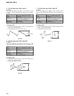
2) Confirm that the Y level is 1.0
±
0.05 Vp-p.
Fig. 6-5
6. Checking Component Video Output B-Y
<Purpose>
This checks component video output B-Y. If it is incorrect, correct
colors will not be displayed when connected to, for instance, pro-
jector.
Mode
Video level adjustment in test mode
Signal
Color bars
Test point
COMPONENT VIDEO OUT (P
B
/C
B
)
connector (75
Ω
terminated)
Instrument
Oscilloscope
Specification
A = 646
±
50 mVp-p
Checking method:
1) In the test mode initial menu “6” Video Level Adjustment, set
so that color bars are generated.
2) Confirm that the B-Y level is A.
Fig. 6-6
7. Checking Component Video Output R-Y
<Purpose>
This checks component video output R-Y. If it is incorrect, correct
colors will not be displayed when connected to, for instance, pro-
jector.
Mode
Video level adjustment in test mode
Signal
Color bars
Test point
COMPONENT VIDEO OUT (P
R
/C
R
)
connector (75
Ω
terminated)
Instrument
Oscilloscope
Specification
B = 646
±
50 mVp-p
Checking method:
1) In the test mode initial menu “6” Video Level Adjustment, set
so that color bars are generated.
2) Confirm that the R-Y level is B.
Fig. 6-7
1.0
±
0.05 Vp-p
A
B

