


HDR-CX190/CX190E/CX200/CX200E/CX210/CX210E/PJ200/PJ200E/PJ210_L2
2-9
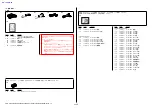
Ref. No.
Part No.
Description
Ref. No.
Part No.
Description
#1
LCD901
#11
313
(Note 2)
301
302
315
314
303
304
305
306
307
308
309
311
312
310
(Note 1)
Screw
Note
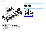
301
A-1851-286-A PD-457 BOARD, COMPLETE
302
4-411-945-01
INSULATING SHEET (2781)
303
4-411-943-01
FRAME (2781), LCD
304
4-411-950-01
CUSHION (2781), LCD
305
4-411-938-01
PLATE (2781), LCD GROUND
306
4-411-948-01
CABINET (M (2781)), P
307
4-411-942-01
KNOB (2781), FOCUS
308
4-411-940-01
COVER (M (2781)), HINGE
309
X-2583-210-1
HINGE(P)(Y(2781))ASSY, T TYPE
310
1-471-598-11
MAGNET (Note 1)
311
4-411-934-01
COVER (C (2781)), HINGE
312
4-418-111-01
ORNAMENT (2781), COVER (C)
313
1-884-872-21
FP-1482 FLEXIBLE BOARD (Note 2)
314
4-419-443-01
SHEET (2781), PD RADIATION
315
4-419-444-01
SHEET (2781), PD CONDUCTIVE
LCD901 A-1854-057-A LCD
BLOCK
ASSY
#1
2-635-562-11 SCREW
(M1.7)
#11
3-078-890-11 SCREW,
TAPPING
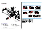
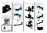
2-1-7. CABINET (R) SECTION-2
(Projector
Model)
Refer to page 2-10, 11 about Non Projector Model
Refer to page 2-10, 11 about Non Projector Model
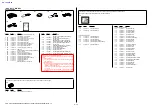
#1: M1.7 X 2.5
(Black)
2-635-562-11
2.5
1.7
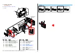
Note 1:
Put the marking side
together on the position
of figure when
you install the magnet.
Marking
Note 1:
マグネットを取付ける
際は,マ−キング面を
図の位置にあわせて
ください。
マーキング
#11: M1.7 X 4.0 (Tapping)
(Silver)
3-078-890-11
4.0
1.7
Note 2:
Refer to “Assembly-3: The Method of attachment o
FP-1482 Flexible Board.”.
Note 2:
“Assembly-3: The Method of attachment of FP-1482
Flexible Board.”
を参照してください。
The changed portions from
Ver. 1.1 are shown in blue.
Ver. 1.2 2012.05


