– 39 –
•
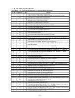
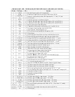
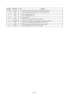
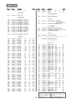
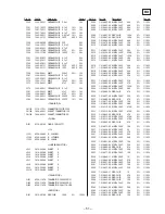
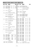
BD BOARD IC102 LC78622E (DIGITAL SIGNAL PROCESSOR, DIGITAL FILTER, D/A CONVERTER)
Pin No.
Pin Name
I/O
Function
1
DEFI
I
Defect detection signal input from the RF amplifier (IC101)
2
TAI
I
PLL test input terminal Not used (fixed at “L”)
3
PDO
O
PLL phase comparison output for external VCO control
4
VVSS
—
Ground terminal (internal VCO system)
5
ISET
I
Connected to a current adjusting resistor for the PDO output
6
VVDD
—
Power supply terminal (+5V) (internal VCO system)
7
FR
I
Adjusts the VCO frequency range
8
VSS
—
Ground terminal (digital system)
9
EFMO
O
Slice level control to EFM signal output
10
EFMIN
I
Playback EFM RF signal input from the RF amplifier (IC101)
11
TEST2
I
Test input terminal (fixed at “L” in this set)
12
CLV+
O
13
CLV–
O
14
V/P
O
Sled servo on/off control signal output to the RF amplifier (IC101) Rough servo/phase control
automatic switching monitor output “H”: rough servo, “L”: phase servo
15
HFL
I
Tracking detection signal input from the RF amplifier (IC101) (Schmitt input) HFL (High
Frequency Level) is used to determine whether the main beam is positioned on a pit or mirror
16
TES
I
Tracking error signal input from the RF amplifier (IC101) (schmitt input)
17
TOFF
O
Tracking off control signal output to the RF amplifier (IC101)
Tracking becomes off when TOFF is “H”
18
TGL
O
Tracking gain control signal output to the RF amplifier (IC101) (Raises gain when “L”)
19
JP+
O
20
JP–
O
21
PCK
O
EFM data playback clock monitor output terminal (4.3218 MHz when phase is locked)
22
FSEQ
O
Sync signal detection output terminal (“H” when a sync signal detected from the EFM signal and
that generated internally coincide)
23
VDD
—
Power supply terminal (+5V) (digital system)
24
CONT1
I
Guard frame sync input terminal
25
CONT2
I
Sled servo on/off control signal input terminal
26
CONT3
O
Sled servo drive control signal output terminal
27
CONT4
I
Sled limit-in detect switch (S101) input terminal The optical pick-up is inner position when “L”
28
CONT5
O
Not used (open)
29
EMPH
O
De-emphasis control signal output terminal
The de-emphasis disc is being played back when “H” Not used (open)
30
C2F
O
C2PO (error condition monitor) signal output terminal
31
DOUT
O
Digital signal output terminal (EIAJ format)
32
TEST3
I
Test input terminal (fixed at “L” in this set)
33
TEST4
I
Test input terminal (fixed at “L” in this set)
34
NC
—
Not used (open)
35
MUTEL
O
Line muting on/off control signal output terminal (for L-ch side) “H”: muting on
36
LVDD
—
Power supply terminal (+5V) (L-ch D/A converter system)
37
LCHO
O
Analog audio signal output from the internal D/A converter block (for L-ch side)
38
LVSS
—
Ground terminal (L-ch D/A converter system)
39
RVSS
—
Ground terminal (R-ch D/A converter system)
40
RCHO
O
Analog audio signal output from the internal D/A converter block (for R-ch side)
41
RVDD
—
Power supply terminal (+5V) (R-ch D/A converter system)
Disc motor control signal output to the RF amplifier (IC101)
(3-value output available depending on the command)
Track jump control signal output to the RF amplifier (IC101)
(3-value output available depending on the command)

