2-2
MVC-CD250/CD400
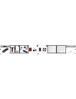
2-1. SIDE CABINET BLOCK ASSEMBLY
Note:
Follow the disassembly procedure in the numerical order given.
3
Open the CD cabinet.
1
Screw (M2)
2
Screw (M2)
4
Two screws (M2)
5
Side cabinet block assembly
Note: Remove it while taking care as
the flexible board is connected.
6
FP-482 flexible board
(CN718)
2-2. CABINET (REAR) BLOCK ASSEMBLY
5
Open the battery lid.
6
Cabinet (rear) block assembly
3
Two screws (M2)
4
Screw
(M2)
1
FP-484 flexible board
(CN724)
7
Harness (SS-084)
(CN719)
8
Harness (microphone)
(CN702)
2
FP-485/FP-486 flexible board
(CN651)
Summary of Contents for CD Mavica MVC-CD250
Page 33: ...Schematic diagram of the SY 76 board are not shown Pages from 4 15 to 4 40 are not shown ...
Page 43: ...Printed wiring board of the SY 76 board are not shown Pages from 4 57 to 4 60 are not shown ...
Page 51: ...Waveforms of the SY 76 board are not shown Pages 4 74 and 4 75 are not shown ...
Page 55: ...Mounted parts location of the SY 76 board are not shown Page 4 79 is not shown ...
Page 57: ...MVC CD250 CD400 5 1 COVER COVER SECTION 5 ADJUSTMENTS ...
Page 121: ...Electrical parts list of the SY 76 board are not shown Pages from 6 15 to 6 23 are not shown ...


