11 (E)
This switcher performs self-diagnosis testing when you
turn the power on or reset the switcher, and at regular
intervals during operation. If the self-diagnosis test
detects an error, the status indicator lights, and
information about the error is output to the terminal.
The information about the error is also output to the
host computer of the ISR system if this switcher is
connected to the system. You can easily determine the
..
Error Indications and Countermeasures
origination of the error through the 2-digit error code
shown on the ERROR NO. indicator on the CPU-94
board. The errors that may be displayed on the
switcher and their respective countermeasures are
shown in the table below.
Refer to the maintenance manual for information
concerning the error codes displayed on the ERROR NO.
indicator and the appropriate countermeasures.
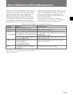
Meanings of status indications and countermeasures for errors
Ask a Sony service personnel for replacing the CPU board
and power supply unit.
Indicator
Meaning
Countermeasures
Lit in green
Switcher operations are normal.
—
Flashing in green
A synchronizing signal was not detected.
Supply a reference video signal.
Lit in red
Both the CPU-94 and BKDS-RS1690 have
The active board is indicated by the D:5 ACT indicator lit.
been installed but there is a problem with
The ACT indicator of the failed board has gone off. Replace
one of the boards. the failed board with a new one and the corresponding ACT
indicator lights green again.
Two power supply units are installed, but
Replace the power supply unit on which the +5V or –5V
one of the voltages is low.
power indicator is not lit.
Flashing in red
One of the following errors was detected
Find the source of the error using the control terminal
during self-diagnosis.
display or error indication.
• The fan stopped working.
• An S-BUS link cable is cut.
Not lit
The power supply unit is not installed
If the power supply unit is failed, replace it.
or it is failed.


