7 (E)
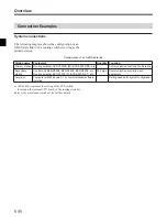
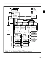
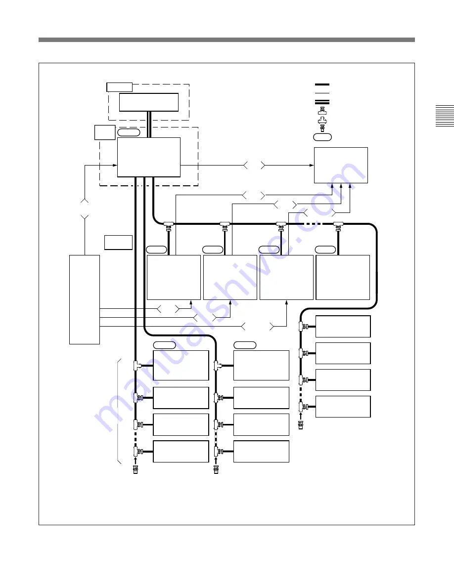
• Only one of the REMOTE 1 connectors on a routing switcher designated as a secondary station can be used.
• A maximum of 128 secondary stations can be connected on one S-BUS line.
• A maximum of three S-BUS lines and 253 secondary stations can be connected to the primary station.
Example of system connections
F
S-BUS
F
Signal Line
F
RS-232C
F
T Bridge (A)
F
T Bridge (B)
F
75
Terminator
F
Matrix Level
Terminal
Primary
Station
Secondary
Station
Level 1
Level 1
Level 1
REMOTE 3
Computer with Windows 3.1
or communication
software installed
Digital Video
Routing Switcher
DVS-V3232B
(M)
Source
VTR
REMOTE 1
REMOTE 1
REMOTE 1
Destination
VTR
Video
Time Code
Audio
Time Code
Video
Audio
Analog Video
Routing Switcher
BVS-V3232
(S)
Analog Audio
Routing Switcher
BVS-A3232
(S)
Time Code
Routing Switcher
DVS-TC3232
(S)
Routing Switcher
(S)
128
max.
Digital Video
Routing Switcher
DVS-V3232B
(S)
Remote Control Unit
BKS-R3202
Remote Control Unit
BKS-R3204
Remote Control Unit
BKS-R3204
Digital Video
Routing Switcher
DVS-V3232B
(S)
Remote Control Unit
BKS-R3204
Remote Control Unit
BKS-R3205
Remote Control Unit
BKS-R3205
Remote Control Unit
BKS-R3206
Remote Control Unit
BKS-R3206
Remote Control Unit
BKS-R3281
Remote Control Unit
BKS-R3280
Level 2
Level 3
Level 4
Level 8
Video
Video


