background image

5

インプットアダプターの取り付けは、

1

 電源ブロック

2

 GC基板

3

 Bブロック

の順序で行います。

インプットアダプターを取り
付ける前に

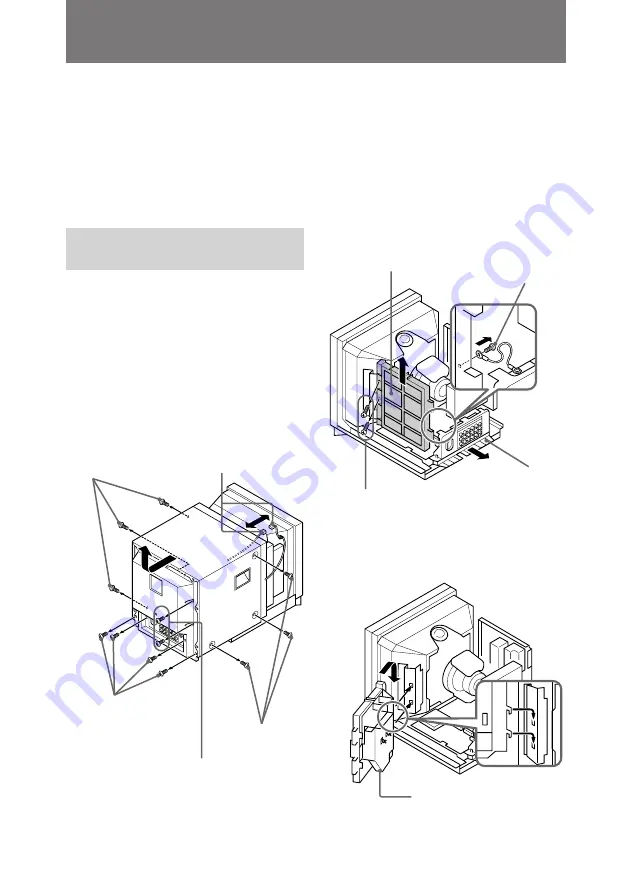
1

モニターのリアカバーを固定している

12本のネジをはずし、リアカバーにつ

いているファンのコネクターをはず

す。

2

リアカバーを、

後ろへスライドさせなが

ら上に持ち上げ、

取りはずす。

3

メインブラケット部を手前に少し引き

出し、

G基板についているネジをはずし

て端子板とG基板をつないでいるケー

ブルをはずす。

(PHM-20M7Jのみ)

4

G基板のネジをはずしてG基板を一度

取りはずす。

5

本体側のフックに下図のようにG基板

を取り付ける。

5

ネジ

BVTT4

×

8

2

本)

3

4

G

基板

メイン
ブラケット部

G

基板

インプットアダプターの取り付けかた

ファンコネクター

ネジ

BVTP4

×

16

4

本)

ネジ

M4

×

8

3

本)

ネジ

BVTT4

×

12

2

本)

1

2

ネジ

M4

×

8

3

本)

ネジ

BVTP3

×

12

Summary of Contents for BKM-301HD

Page 1: ...買い上げの特約店にお任せくだ さい モニター内部には高電圧部が数多くあり 万一触れると 危険 ですので お客様自身では絶対に取り付けを行わないでください 特約店の方は 取り付けを安全に行うために 必ずこの取付説明書 をよくお読みください This manual is intended for dealers Leave installation of the BKM 301HD to your authorized Sony dealer The monitor has many components inside that have extremely high voltage Touching these may lead to injury Do not install this input adaptor by yourself Authorized dealers must re...

Page 2: ...機製品はまちがった取り扱いかたをすると 火 災や感電などにより死亡や大けがなど人身事故につながる ことがあり 危険です 取り付けを安全に行うために 必ずこの取付説明書をよく お読みください 取り付けの際は感電を防ぐため 次の項目をお守りくださ い モニターの電源を切る モニターに接続されている電源コードなど全ての接続 ケーブルをはずす 警告 警告 注意 警告 注意 警告表示の意味 取付説明書および製品 では 次のような表示 をしています 表示の 内容をよく理解してか ら本文をお読みくださ い この表示の注意事項を 守らないと 火災や感 電などにより死亡や大 けがなど人身事故につ ながることがありま す この表示の注意事項を 守らないと 感電やそ の他の事故によりけが をしたり周辺の物品に 損害を与えたりすること があります ...

Page 3: ...3 部品表 4 インプットアダプターの取り付けかた 5 インプットアダプターを取り付ける前に 5 電源ブロックの取り付けかた 6 GC基板の取り付けかた 7 Bブロックの取り付けかた 8 インプットアダプターをすべて取り付けたら 10 ステータス サービスモード の書き換えかた 11 目次 日 本 語 J ...

Page 4: ...4 GC基板 BNC端子x2 BNC端子用ワッシャーx2 BNC端子用ナットx2 基板ホルダーx4 電源ブロック Bブロック 8ピン接続ケーブル 電源ブロック用ネジ3x8 1本 部品表 ...

Page 5: ...いているファンのコネクターをはず す 2 リアカバーを 後ろへスライドさせなが ら上に持ち上げ 取りはずす 3 メインブラケット部を手前に少し引き 出し G基板についているネジをはずし て端子板とG基板をつないでいるケー ブルをはずす PHM 20M7Jのみ 4 G基板のネジをはずしてG基板を一度 取りはずす 5 本体側のフックに下図のようにG基板 を取り付ける 5 ネジBVTT4 8 2本 3 4 G基板 メイン ブラケット部 G基板 インプットアダプターの取り付けかた ファンコネクター ネジ BVTP4 16 4本 ネジM4 8 3本 ネジ BVTT4 12 2本 1 2 ネジM4 8 3本 ネジBVTP3 12 ...

Page 6: ...はず す 2 シールドケースをはずした電源ブロッ クを G基板のシールドケースの図の 位置に引っかけ 付属のネジ 3 8 を 使用して固定する 3 手順1ではずした電源ブロックのシー ルドケースを再びネジで取り付ける 4 電源ブロックの接続ケーブル 黒 白 と 黒 赤 を図のように2つのパース ロックで固定し 接続ケーブル 黒 白 をG基板のCN610端子へ接続する インプットアダプターの取り付けかた 1 2 電源ブロック G基板 ネジ3 8 付属 ネジPS3 8 シールドケース パースロック CN610 ...

Page 7: ...ブロックを取 り付けた後に行ってください 1 メインブラケット部を 手前にスライ ドさせるようにして引き出す 2 A基板左前方にあるシールドケースの ふたを 垂直に持ち上げて取りはずす 3 取りはずしたシールドケースのふたに ある四隅の穴に基板ホルダー 付属 を 差し込む その基板ホルダーとGC基板の四隅の 穴を合わせ GC基板を押し込んで取り 付ける つづく 続く シールドケース のふた メイン ブラケット部 A基板 1 2 GC基板 基板ホルダー 付属 4個 ...

Page 8: ...ケースのふたを再び取り付け る 6 GC基板のCN2端子とA基板のCN4002 端子を付属の8ピン接続ケーブルで接 続する インプットアダプターの取り付けかた 5 4 CN1 CN2 CN4002 8ピン接続ケーブル 付属 ご注意 Bブロックの取り付けは 電源ブロックお よびGC基板を取り付けた後に行ってくだ さい 1 コネクターパネル部右側のパースロッ クで固定しているケーブルと 4か所の 端子 CN3 CN4 CN5 CN601 に接続 しているケーブルをはずしておく CN3 CN4 CN5 CN601 Bブロックの取り付けかた ...

Page 9: ...ずし コネクターパネルカバーを取 りはずす 4 コネクターパネルカバーの裏側から BNC端子を取り付ける穴をニッパー などを使用して2か所あける 5 端子板の裏側から 2か所の穴に2本の BNC端子 付属 を通し 表側から各端 子にワッシャーを入れ ナットで固定 する 6 コネクターパネルカバーをネジを使用 して端子板に再び取り付ける 7 コネクターパネル部をメインブラケッ ト部にはめ込み 手順1ではずしたケー ブルをそれぞれ元の位置に戻す コネクターパネルカバー BVTP3 8 6本 コネクターパネル部 ナット 付属 BNC端子 付属 ワッシャー 付属 続く ...

Page 10: ... GC基板の CN3端子に接続する Bブロック CN4003 CN4001 A基板 CN3 インプットアダプターをすべて取 り付けたら 1 インプットアダプターを取り付ける前 に の手順5で取り付けたG基板を元の 位置にもどし 2本のネジで固定する 2 インプットアダプターを取り付ける 前に の手順3ではずしたケーブルを つなぎなおし メインブラケット部を しっかり止まるまで前方にスライドさ せて 元の位置にセットする 3 インプットアダプターを取り付ける 前に の手順1ではずしたファンのコ ネクターを モニター本体のコネク ターに差し込み ネジ12本を使用して モニターのリアカバーを取り付ける ご注意 部品の取り付けや配線の引きまわしは 取 り付け前と同じ状態にしてください ご注意 ファンのコネクターをつながないと 電源が入りません ...

Page 11: ...ENU EXITボタンとENTER SE LECTボタンで SDI EXIST 0 216 を画 面に表示させる 4 ボタンで SDI EXIST 0 216 の 0 を 1 にする 5 DEGAUSSボタンを押す WRITE が表示されます ステータス サービスモード の書き換えかた 続く MENU EXIT ENTER SELECT SDI EXIST 0 216 RESET SDI EXIST 1 216 DEGAUSS SDI EXIST 1 216 WRITE MENU EXIT MENU STATUS COLOR TEMP SELECT ADJ SYNC SELECT YPBPR GBR 16 9 4 3 4 3 MARKER ADJ FACTORY PRESET SELECT ENTER MENU ENTER SELECT DEGAUSS BTA 1125 N S H SIZ...

Page 12: ...定が正しく行われると 1 の左側に が表示されます サービスモード のステータスの書き換えはこれで終了 です 7 DEGAUSSボタンとENTER SELECT ボタンをもう一度同時に押す サービスモードから出ます 8 INPUT C入力切り換えスイッチを押 して インジケーター オレンジ が点 灯することを確認する HD SDI信号を入力できます ステータス サービスモード の書き換えかた ENTER SELECT DEGAUSS INPUT C DEGAUSS SDI EXIST 1 216 WRITE ...

Page 13: ...14 Installing the Input Adaptor 15 Before Installing the Input Adaptor 15 Installing the Power Block 16 Installing the GC board 17 Installing the B block 18 After Installing the Input Adaptor 20 Rewriting the Service Mode Status 21 EN Englsih ...

Page 14: ...14 Components Power block GC board BNC connector 2 B block 8 pin connector cable Power block screw 3 8 1 BNC washer 2 BNC nut 2 Board holder 4 ...

Page 15: ...ear cover 2 Slide the rear cover back then lift and remove it 3 Pull the main bracket forward a little Remove the screws on the G board and remove the cable between the terminal board and the G board PHM 20M8U 4 Remove the screws on the G board and remove the G board 5 Install the G board as figure below 1 2 Fan connector Screw M4 8 3 Screw BVTP4 16 4 Screw BVTT4 12 2 Screw M4 8 3 3 4 G board Scre...

Page 16: ...ield case see figure Lock the power block with the screw 3 8 supplied 1 2 3 Install the power block shield case removed in Step 1 Lock the case with the screw 4 Lock the power block cables black white and black red with the two purselocks see figure Connect the cable black white to the CN610 connector on the G board Screw PS3 8 Screw 3 8 supplied Shield case G board Power block CN610 Purselocks ...

Page 17: ...in bracket 2 Lift and remove the shield case lid left front of the A board 3 Insert the board holders supplied into the four holes in the shield case Match the board holders and the holes of the GC board insert the GC board into the holes 1 2 Shield case lid A board Main bracket GC board Board holders supplied 4 Continued ...

Page 18: ...onnector on the GC board and the CN4002 connector on the A board with the 8 pin cable supplied 5 4 CN1 8 pin cable supplied CN2 CN4002 Installing the B block Note Install the B block after you have installed the power block and the GC board 1 Remove the following cables Cable that has been locked by the purselock on the right side of the connector panel Cables that connected to 4 connectors CN3 CN...

Page 19: ...es are for installing the BNC connectors Use pinch pliers as needed 5 From the back of the connector board insert the two BNC connectors supplied through the two holes From the front of the connector board insert the washers Lock the connectors with the nuts 6 Use the screws to install the connector panel cover on the connector board 7 Insert the connector panel in the main bracket Reconnect the c...

Page 20: ...oard installed in Step 5 in Before Installing the Input Adaptor to the original location Lock the board with the two screws 2 Reconnect the cables removed in Step 3 in Before Installing the Input Adaptor Slide the main bracket back into the unit until it is set in the original place 3 Insert the fan connector removed in Step 1 in Before Installing the Input Adaptor into the monitor connector Use t...

Page 21: ...e time The service mode status menu appears MENU EXIT MENU STATUS COLOR TEMP SELECT ADJ SYNC SELECT YPBPR GBR 16 9 4 3 4 3 MARKER ADJ FACTORY PRESET SELECT ENTER MENU ENTER SELECT DEGAUSS BTA 1125 N S H SIZE 238 3 MENU EXIT ENTER SELECT SDI EXIST 0 216 3 Press the MENU EXIT and ENTER SELECT buttons as needed to display SDI EXIST 0 216 on the screen 4 Using the button change 0 to 1 in SDI EXIST 0 2...

Page 22: ...completed appears to the left of 1 This indicates that the service mode status has been rewritten 7 Press the DEGAUSS and ENTER SELECT buttons at the same time This terminates the service mode 8 Press the INPUT C switch Make sure the indicator orange has been turned on You can input the HD SDI signals ENTER SELECT DEGAUSS INPUT C Rewriting the Service Mode Status ...

Page 23: ...23 ...

Page 24: ...231 8121 営業所 022 257 7830 営業所 048 652 8808 出張所 025 270 3253 営業所 043 297 8531 営業所 03 5448 6740 営業所 042 575 0201 出張所 0263 25 4551 営業所 045 243 6711 営業所 054 284 3601 営業所 052 201 6871 営業所 076 240 8110 営業所 075 691 7860 営業所 06 531 4111 営業所 078 322 0851 営業所 082 241 9211 営業所 087 831 3003 営業所 092 741 2761 Printed in Japan 東京システム営業所 03 5448 6740 システム営業1部 2部 03 5448 5446 ...

Reviews: