Recording
Chapter 2 Recording and Playback
20
Chapter 2
Recording and Playback
4
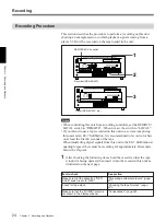
When the REMOTE/LOCAL switch is set to “LOCAL”, use the
COUNTER SELECT button to select the type of time data to be used.
Each press of this button cycles through three options: COUNTER
(CNT value), TC (time code), and U-BIT (user bit data). The time
data type indicator for each option lights as it is selected.
When the REMOTE/LOCAL switch is set to “REMOTE”, selection of
the time data type is carried out at the editing controller.
5
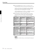
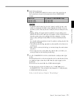
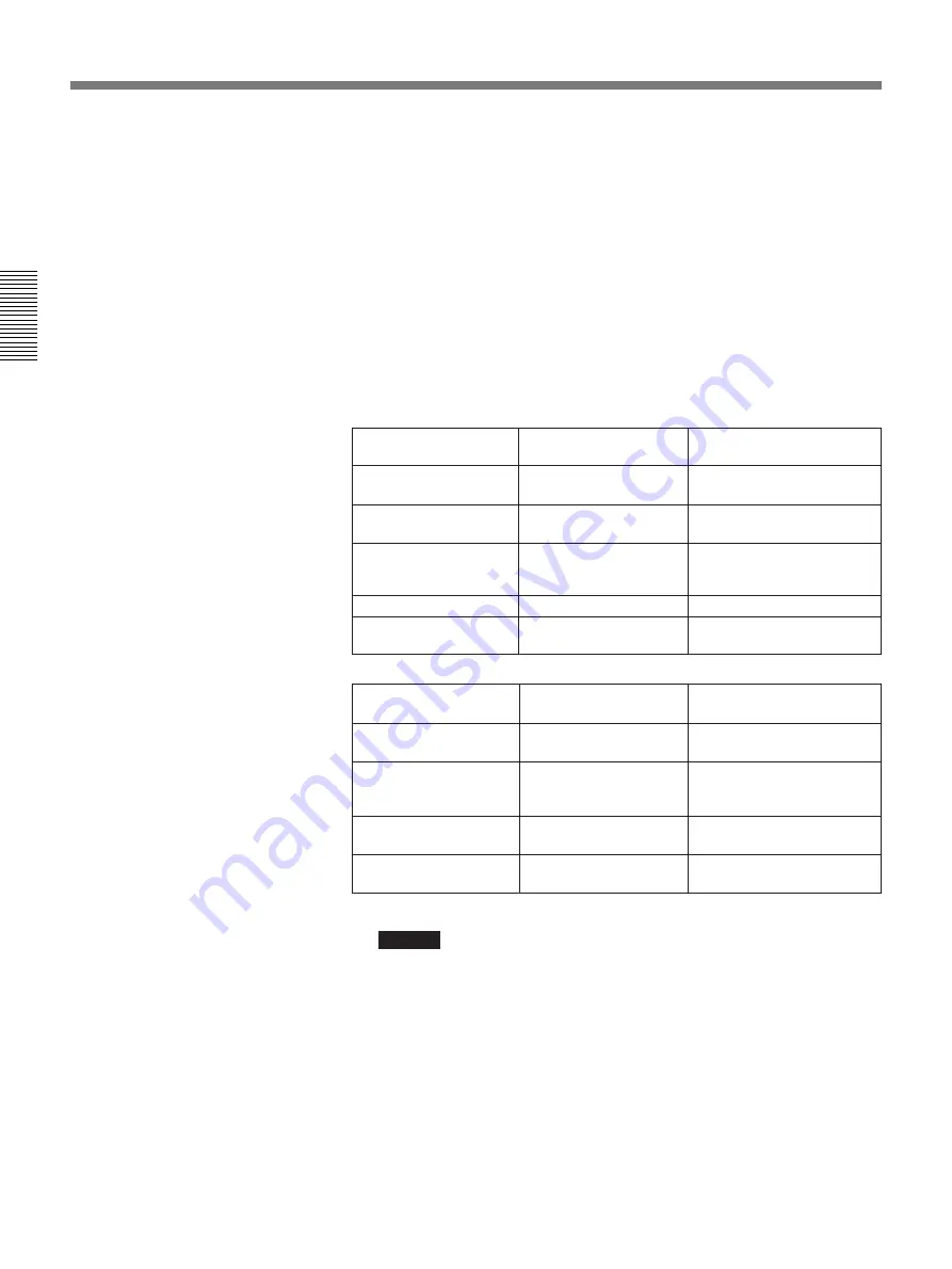
Select the formats of video and audio input signal to be recorded.
Press INPUT SELECT buttons to select the desired signal formats.
Each selection is shown by a lit indicator in the INPUT MODE
display.
Caution
Once you have started recording, you cannot change the input signal
selection.
QSDI
Video input signal
(input connector)
Corresponding INPUT
SELECT button
Lit indicator in INPUT
MODE display
VIDEO
COMPOSITE in VIDEO
group
Separated Y/C signal
(S VIDEO IN)
VIDEO
S VIDEO in VIDEO group
Composite signal
(VIDEO IN)
Component signal
(COMPONENT VIDEO
IN)
VIDEO
COMPONENT in VIDEO
group
SDI signal (SDI INPUT)
VIDEO
SDI in VIDEO group
QSDI signal (QSDI
INPUT)
QSDI
QSDI
Audio input signal
(input connector)
AUDIO CH-1 CH-1/2,
AUDIO CH-2 CH-3/4
QSDI signal (QSDI
INPUT)
Corresponding INPUT
SELECT button
Lit indicator in INPUT
MODE display
Analog signal (AUDIO
IN CH-1 to CH-4)
ANALOG in AUDIO group
AES/EBU signal
(DIGITAL AUDIO
(AES/EBU) INPUT)
AUDIO CH-1 CH-1/2,
AUDIO CH-2 CH-3/4
AES/EBU in AUDIO group
SDI signal (SDI INPUT)
AUDIO CH-1 CH-1/2,
AUDIO CH-2 CH-3/4
SDI in AUDIO group
QSDI


