


Developer's Board Manual Rev A
Page 22 of 28
SEM/CX-02:0061/MAN
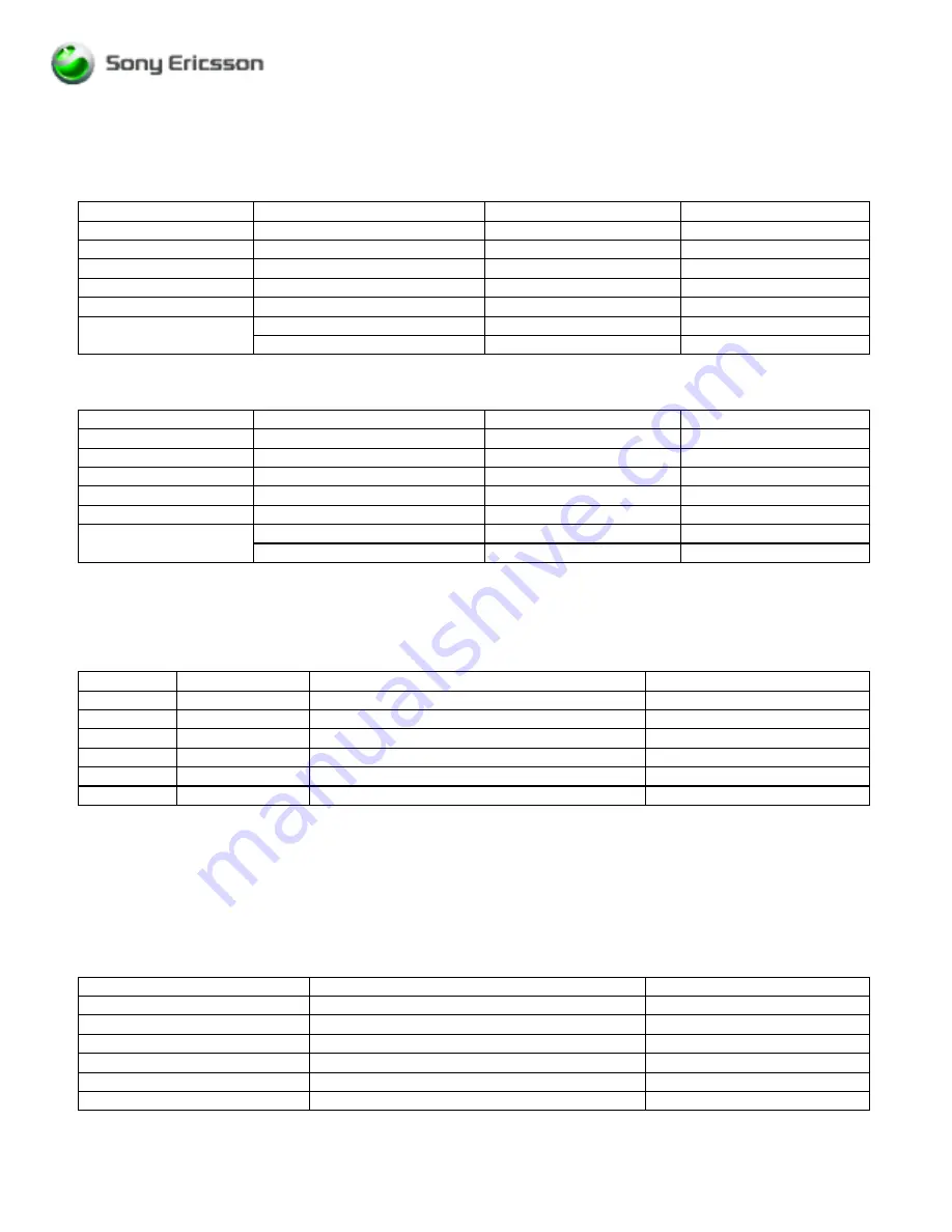
Hardware Flow Control Mechanism is provided via the signals CTS, DTR and RTS. Flow control is used for CSD
applications. To activate or de-activate the Flow Control mechanism, switch S3 must be set as presented in
Table 7 and Table 8 respectively.
Switch Position
Function
DM-xx
CM-4x
Position 1
DTMS
ON
ON
Position 2
CTS
ON
ON
Position 3
DTR
ON
ON
Position 4
DFMS
ON
ON
Position 5
RTS
ON
ON
Module_Pwr_En_B
ON
Position 6
WAKE
OFF
Table 19: S3 Settings to enable HW Flow Control
Switch Position
Function
DM-xx
CM-4x
Position 1
DTMS
ON
ON
Position 2
CTS
OFF
OFF
Position 3
DTR
OFF
ON
Position 4
DFMS
ON
ON
Position 5
RTS
OFF
OFF
Module_Pwr_En_B
ON
Position 6
WAKE
OFF
Table 20: S3 Settings to disable HW Flow Control
If you intend to use the serial interface using the header connector provided on the developer’s board, notice that
appropriate CMOS voltage levels as defined by VDIG in §3.3 Power Interface shall be connected to the
appropriate pins as follows:
Pin
Signal
Description
Direction
23
DCD
Data Carrier Detect
O
25
CTS
Clear To Send
O
26
DTR
Data Terminal Ready
I
27
TD
Serial Data To Module (DTMS)
I
28
RTS
Request To Send
I
30
RD
Serial Data From Module (DFMS)
O
Table 21: Direction of Serial Data Signals
If this type of interface is to be used, positions 1,2, and 4 of S3 must be set to OFF to prevent damage to the RS-
232 transceivers, N1 and N2.
3.7 System Connector Header
The system connector header is used when the application wants direct access to any particular pin available in
the system interface of the module (i.e., digital audio pins).
Switch
Position Function
ON/OFF
Position 1
DTMS
OFF
Position 2
CTS
OFF
Position 3
DTR
OFF
Position 4
DFMS
OFF
Position 5
RTS
OFF
Position 6
MODULE_PWR_EN_B / WAKE
OFF