C702
1221-7857 rev. 1
APPENDIX
A
P
P
E
NDIX
Troubleshooting Fixture Setup Instructions
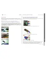
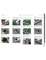
Connect Display if needed, according to picture
13.
Picture 13
Place the Display on TRS Fixture according to
picture 14.
Picture 14
Lock the Display with locking screw according to
picture 15.
Picture 15
Connect the Keypad Flex Cable to the board-to-
board connector mounted on the PBA when
Keypad is in use according to picture 16.
Picture 16
Connect Power Supply Channel 2 DCIO/SEPI
Cable according to picture 17.
Picture 17
Secure the DCIO/SEPI Cable by using the screw
according the picture 18.
Picture 18
Connect SMK RF Probe to the PBA by using RF
Connector Frame according to picture 19.
Picture 19
Secure the SMK RF Probe with the RF Probe
locking device (RF Connector) according to
picture 20.
Picture 20
Connect the Customized FM Radio Cable
according to Step 1 and Step 2.
Step 1:
Connect the Black Lab Plug to the TRS Fixture
GND input according to picture 21.
Picture 21
Step 2:
Connect the Hands-Free (PHF) connector to he
Phone system connector (X2300) according to
picture 22.
Picture 22
Please see the picture 23 for the final Customized
FM Radio Cable connection setup with the TRS
Fixture.
Picture 23
The Pin mounted inside of the TRS Fixture
marked with “RED” arrow can be used as
MP TRS Fixture GND or grounding for the
oscilloscope probe, see picture 24.
Picture 24
SEMC Troubleshooting Manual
115
(115)
Summary of Contents for C702
Page 116: ...www s manuals com ...

