background image

6

3 – Drive Mode Descriptions

RAID 5: Striping, Parity Distributed Among Drives

RAID 5 configuration increases reliability while using fewer 
drives than RAID 10 mirroring by using parity redundancy: 
parity is distributed across multiple drives. Any one of 
the four drives can fail, and the volume will continue to 
function. See 

Figure 13

. When the failed drive is replaced, 

the parity data on the three other drives is used to rebuild 
the RAID volume with data spread across all four drives.

In the QR, RAID 5 configuration offers 75% of the four 
drives’ total capacity. For example, if your system has four 
4TB drives, the total unformatted capacity is 16TB. After 
configuring the drives in RAID 5 mode, approximately 12TB 
is available for storage, with the other 4TB set aside for parity.


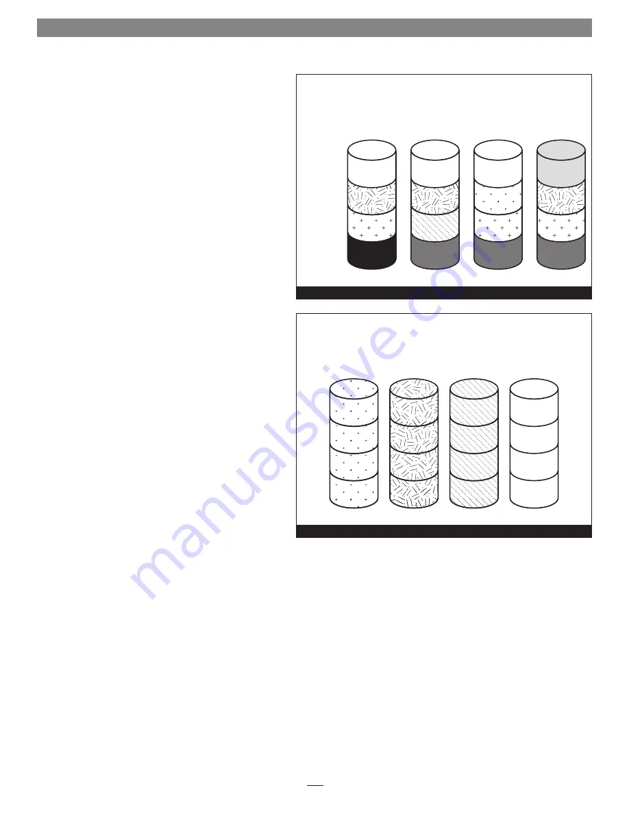
JBOD: Just a Bunch of Disks

JBOD mode enables all four drives to be available 
individually at the same time for normal storage operations. 
See 

Figure 14

Note that when you connect the QR to your 

computer via eSATA connection, the eSATA controller to which 
the storage system is connected must offer port multiplier 
support
; refer to the eSATA controller’s documentation or 
the manufacturer’s Website for information. If the eSATA 
controller does not offer port multiplier support, only one 
of the four drives will be accessible. 

JBOD provides no data 

protection

.

JBOD offers the full capacity of each of the drives.

Disk 1

Data 1

Data 5

Data 9

Parity

10–12

Disk 2

Data 2

Data 6

Parity 7–9

Data 10

Disk 3

Data 3

Parity 4–6

Data 7

Data 11

Disk 4

Parity 1–3

Data 4

Data 8

Data 12

RAID 5:

Striping, Parity Distributed Among Drives

Stripe 1

Stripe 2

Stripe 3

Stripe 4

Figure 13

Disk 1

Data 1

Data 2

Data 3

Data 4

Disk 2

Data 5

Data 6

Data 7

Data 8

Disk 3

Data 9

Data 10

Data 11

Data 12

Disk 4

Data 13

Data 14

Data 15

Data 16

JBOD (Just a Bunch of Disks)

Figure 14

Summary of Contents for Fusion QR

Page 1: ...4 Drive Hardware RAID 5 SATA Disk Enclosure with Quad Interface FUSION QR User s Guide For Windows ...

Page 2: ......

Page 3: ...e Mode Configuration Change Drive Mode 5 Drive Formatting Instructions 8 OS X Users Instructions Windows Users Instructions 6 Status LED Indications 9 System Powered No Drive Activity Drive Activity Drive Not Recognized RAID 5 or RAID 10 Rebuild Bad Drive Detected 7 Specifications Warnings and Additional Information 10 Specifications Warnings FCC Compliance Contacting Customer Serrvice Visit Our W...

Page 4: ......

Page 5: ... hold this switch for three or more seconds upon powering the system to activate the selected drive mode 6 Drive Trays To remove a drive tray turn the thumbscrew counter clockwise until it pops out and then pull out the entire tray To place a drive tray insert it into the drive bay until it stops push in the thumbscrew until it stops and then turn it clockwise until it stops do not overtighten the...

Page 6: ...om the back until it stops Figure 2 3 Pull the front panel toward you and then lift it off of the enclosure Figure 3 Set the panel aside 4 Turn a drive tray s thumbscrew counter clockwise until it pops out and then pull out the tray by the thumbscrew Figure 4 2 Drive Installation and Enclosure Setup 2 Figure 2 Figure 1 Figure 4 Figure 3 push the inner chassis in until it stops pull out the top edg...

Page 7: ...ws Figure 7 8 Carefully slide the drive module into the enclosure until it stops push in the thumbscrew and then turn it clockwise to secure the module in place do not overtighten the screw Figure 8 9 Repeat steps 5 8 for each remaining drive WARNING When handling computer products take care to prevent components from being damaged by static electricity avoid working in carpeted areas Handle hard ...

Page 8: ... plugged in securely Figure 9 4 Do not turn on the QR s power yet you must first follow the instructions to select the drive mode Go to the next page for descriptions of the various configuration modes available or skip to page 7 for directions on how to set the drive mode 2 Drive Installation and Enclosure Setup 4 Support Note The supplied Sonnet locking eSATA cable is compatible with all eSATA p...

Page 9: ... Levels 1 and 0 See Figure 11 RAID 10 offers 50 of the total capacity of the four drives Span Concatenation Volume Spans Four Drives Span mode creates a single large volume that spans all four drives writing files to the capacity of the first drive then the second drive and so on See Figure 12 Span mode provides no data protection When configured as a spanned volume the total volume size depends o...

Page 10: ...e enables all four drives to be available individually at the same time for normal storage operations See Figure 14 Note that when you connect the QR to your computer via eSATA connection the eSATA controller to which the storage system is connected must offer port multiplier support refer to the eSATA controller s documentation or the manufacturer s Website for information If the eSATA controller...

Page 11: ... Mode You may change the drive mode from its initial state to another by following the steps listed in Initial Drive Mode Configuration above WARNING Configuring the drives in your Fusion QR enclosure results in them having to be reformatted Reformatting the drives will erase any data on them If there is any data on them back it up first outside of the Fusion system before configuring the drives W...

Page 12: ... Storage on the left and then double click Disk Management 3 When the Initialize Disk window appears select the RAID volume you created Select the MBR partition style if you need to access your RAID storage from a computer running Windows XP Professional or 32 bit Windows Server 2003 otherwise select GPT Click OK 4 In the Disk Management window the Fusion QR s drives will appear listed as unalloca...

Page 13: ...e as soon as possible RAID 5 or RAID 10 Rebuild After inserting a drive into the QR enclosure to replace a failed drive from a RAID 5 or RAID 10 group the corresponding LED alternately flashes orange and green until the RAID has been rebuilt Figure 23 Once the rebuild is complete the LED returns to normal operation Bad Drive Detected When the QR determines a drive has gone bad the corresponding LE...

Page 14: ... from the electrical outlet Follow the instructions in this manual carefully contact your reseller or local distributor for additional advice not covered in this User s Guide FCC Compliance Fusion QR complies with Part 15 of the FCC Rules Operation is subject to the following two conditions This device may not cause harmful interference AND this device must accept any interference received includi...

Reviews: