background image

SonicWall Switch Getting Started Guide

Configuring from the Firewall

47

4 In the 

IP Address 

field, type in any private IP address that does not interfere with the IP address range of 

any other interfaces on the appliance.

5 Enter  a 

Subnet Mask

. The default is 255.255.255.0.

6 Use the default settings or select appropriate settings for the other fields and then click 

OK

.

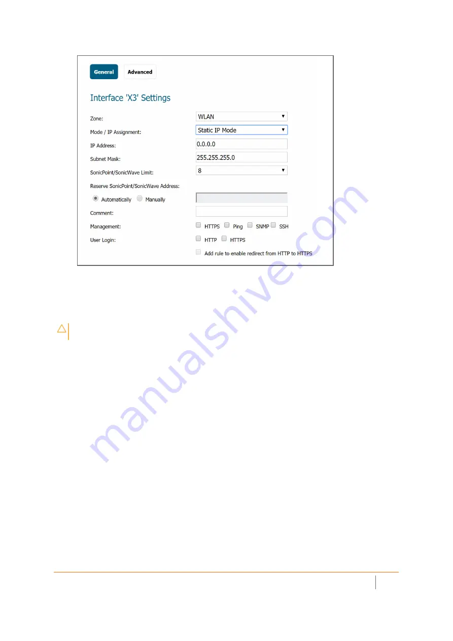
To Configure the WLAN Zone:

1 In the 

MANAGE

 view on the 

System Setup | Network > Zones

 page, click the 

Edit

 icon in the 

Configure


column of the 

WLAN


row.

CAUTION: 

Allowing Management and User Login to the appliance from a wireless zone can pose a security 

threat if you or your users have not set strong passwords.

Summary of Contents for SWS12 Series

Page 1: ...SonicWall Switch Getting Started Guide...

Page 2: ...20 Configuring from the Firewall 22 Firewall Switch Controller UI 22 Before Adding a Switch 23 Checking Switch Details 23 Adding a Switch to a Firewall with Zero Touch 24 Adding a Switch to a Firewall...

Page 3: ...uring a Dedicated Uplink 61 Configuring a Hybrid System with Common and Dedicated Uplink s 63 Configuring Isolated Links for Management and Data Uplinks 64 Configuring HA and PortShields With Dedicate...

Page 4: ...o your MySonicWall account If you do not have an account create one at https www mysonicwall com 3 Navigate to MyWorkspace Register Products and go through the steps 4 When you add a Switch at the fir...

Page 5: ...des simple yet powerful PoE manageability with features such as IEEE 802 3af or IEEE 802 3at af ports PoE port management voice VLAN QoS static routing 802 1x authentication and access point managemen...

Page 6: ...omains The Switch provides the Wired Security and also enhances port density Use it to segment a network into different VLANs or zones The Switch also supports access points which provides Wireless Se...

Page 7: ...es can be managed from a SonicWall firewall WiFi Cloud Manager or directly from on premises or cloud based systems From top to bottom the models are SWS12 8 SWS12 8PoE Check Package Contents Check tha...

Page 8: ...SFP Ports Small Form Pluggable ports 1 Gbps 4 PoE Mode LED Off PoE mode off Lit PoE mode on 12 SFP Link Act LED per SFP port Off No link Solid Green active1 Gbps link Blinking packet transfer in proc...

Page 9: ...this booklet your package includes SonicWall Switch 2 rack mounting brackets with 8 screws Serial cable Safety Environmental and Regulatory Information booklet Power cable in figure above 10 A minimu...

Page 10: ...current 3 Fault LED Off normal Lit Fault 10 Link Activity LED per copper port Off No link Solid Light link on Blinking packet transfer in process 4 PoE Max LED Off Additional PoE device may be added L...

Page 11: ...D Off Additional PoE device may be added Lit PoE power limit exceeded 11 Link Act LED per copper port Off No link Lit link on Blinking packet transfer in process 5 LAN Mode LED Off LAN mode off Lit LA...

Page 12: ...Max LED Off Additional PoE device may be added Lit PoE power limit exceeded 11 Link Act LED per copper port Off No link Lit link on Blinking Light packet transfer in process 5 LAN Mode LED Off LAN mod...

Page 13: ...s For an overview on using SFP SFP refer to SonicWall 10 Gigabit Ethernet SFP Ports and 1 Gigabit Ethernet Ports For a list of third party SFP SFP modules refer to Supported SFP and SFP Modules For a...

Page 14: ...SonicWall SFP SFP modules and ca bles https www sonicwall com customers contact sales 4 4 4 4 Fans 1 2 1 3 Power Supply 180 W 25 W 480 W 60 W 900 W Power Input 100 240 VAC 2 5 A 50 60 Hz 100 240 VAC...

Page 15: ...ct to the Switch Local User Interface 1 Configure an IP address in the 192 168 168 0 24 subnet to access the Switch Local UI 2 Now power up the Switch and wait for it to fully boot Connect an Ethernet...

Page 16: ...To change the password click on the edit icon To add Switch to a network with a DHCP server 1 Go to System Network and click on Action 2 In IPV4 SETTINGS select DHCP 3 Click OK and then connect the Sw...

Page 17: ...ate to Network Routing to establish a static route Connecting via the Console Port Follow these steps to connect with the Command Line Interface for the switch Refer to Hardware Overview on page 7 loc...

Page 18: ...ons as shown below This feature will allow changing the active firmware image after selection here and re booting New firmware can be loaded into the active or inactive partition 2 Click to select the...

Page 19: ...stem Firmware and select upgrade details as below and click on apply 3 Once the Switch has rebooted log back into the Switch and verify the firmware version is properly updated IMPORTANT Once the firm...

Page 20: ...rade 1 If you do not have a TFTP server on your PC download one Below we show one from https tftpd32 jounin net 2 Download the new firmware from software sonicwall com 3 Bring up the TFTP server note...

Page 21: ...ttps www sonicwall com support knowledge base how can i login to the appliance using the c ommand line interface cli 170505641032025 3 Once connected to the Command Line Interface log in Defaults are...

Page 22: ...g a Switch on page 23 List View Setting Up the Ports on page 37 VLAN View Adding a VLAN on page 32 Switches Switch Checking Switch Details on page 23 Networks Adding a VLAN on page 32 Users Setting Up...

Page 23: ...r firewall interface can be portshielded to it The firewall interface linking to the Switch cannot be a PortShield group member that is it cannot be portshielded to another firewall interface Switches...

Page 24: ...ro Touch To prepare firewall 1 Check that the firewall firmware is at the most recent level IMPORTANT Please register your Switch before trying to add it to a firewall See Registering Your Switch on p...

Page 25: ...tch Navigate to Manage Network Interfaces and select an interface then click on Configure and select the Advanced tab Select Enable AutoDiscovery of SonicWall Switches 3 Connect the Switch to the sele...

Page 26: ...h Getting Started Guide Configuring from the Firewall 26 5 Navigate to Manage Switch Controller Overview Click on Authorize button to add the Switch to firewall 6 The network topology will now appear...

Page 27: ...t appears click on Add Switch The dialog box will appear ID The system will auto assign a consecutive number here IMPORTANT Please register your Switch before trying to add it to a firewall See Regist...

Page 28: ...Chain when multiple Switches are added such that no Switch connects with more than two others Switch Management Management traffic flows on this interface Firewall Uplink This is the port on the fire...

Page 29: ...irewall 29 Changing the Switch Configuration Click the three dot box to the right of the switch graphic in the Physical Overview display and then select Edit Check the Status and Link Details Navigate...

Page 30: ...tch configuration details are correct including IP address serial number and Switch Management interface This can also be done by going to Switch Controller Switches and clicking on Configure See Chan...

Page 31: ...itch 1 Simply depress the recessed reset Switch on the front panel for a second OR 1 Click on the 3 dot menu on the Switch image on the Overview page and click on Reboot Switch To reboot the Switch to...

Page 32: ...n By limiting traffic to specific broadcast domains VLANs improve security Each VLAN in a network has an associated VLAN ID which appears in the IEEE 802 1Q tag in the Layer 2 header of packets transm...

Page 33: ...ifies LAN Voice Priority Tag determines priority among active voice streams Differentiated Service Code Point defines QoS Use the Voice VLAN Settings to enable Voice traffic management and determine i...

Page 34: ...uide Configuring from the Firewall 34 To Enable Disable Voice VLAN from the Physical View Simply go to MANAGE Switch Controller Overview and click on the port When the sideband display appears scroll...

Page 35: ...tic route to a Switch 1 Navigate to Switch Controller Switches then select Static Routes and click on Add Static Route 2 Fill out the dialog box Destination IP address with 0 as the last octet x x x 0...

Page 36: ...SonicWall Switch Getting Started Guide Configuring from the Firewall 36 Editing DNS To set DNS addresses go to Switch Controller Switches and select Network then click on Edit DNS...

Page 37: ...To configure specific ports 1 Go to Switch Controller Overview and click on List View This can also be done from the Physical View 2 When the list appears click on the edit button for the specific po...

Page 38: ...queue resulting in uninterrupted actions To set up QoS for a Switch 1 Navigate to Switch Controller Switches and click on QoS 2 Set Egress Policy The first screen details Egress Policy which applies f...

Page 39: ...9 4 To set class of service click on CoS In the CoS Class of Service screen the CoS priority tag values where 0 is the lowest and 7 is the highest are related to eight traffic priority queues from 1 t...

Page 40: ...the PoE module The Device Discovery Protocol lets the device discover powered devices attached to device interfaces and learns their classification Disabled Disables the Device Discovery protocol and...

Page 41: ...Guide Configuring from the Firewall 41 Setting Up Users Users with different access levels admin and user can be defined by navigating to Switch Controller Switches and clicking on Users Users are li...

Page 42: ...d to access resources located on the protected side of the network The Switch uses 802 1X to enable or disable port access control to enable or disable the Guest VLAN and to enable or disable the forw...

Page 43: ...After connecting the child Switch to the parent Switch the Switch will be visible in the Switch Controller Overview page Simply click the Authorize option and the Switch will be added in daisy chain m...

Page 44: ...hot in Step 2 It is the second column in the row for this Switch Parent Switch Uplink Interface on parent Switch which is connected to the child Switch Switch Uplink This is the port through which the...

Page 45: ...ng graphic exemplifies a firewall Switch access point configuration To manage an access point through a Switch this procedure refers to the following diagram 1 Connect Port 1 of Switch to X2 interface...

Page 46: ...ets an IP address from the configured network To do this in the firewall GUI go to Access Points Base Settings and select SonicWave Object For details on configuring the SonicWave object see Configuri...

Page 47: ...Mask The default is 255 255 255 0 6 Use the default settings or select appropriate settings for the other fields and then click OK To Configure the WLAN Zone 1 In the MANAGE view on the System Setup N...

Page 48: ...ireless under SonicPoint SonicWave Settings select Only allow traffic generated by a SonicPoint SonicWave to allow only traffic from SonicPoints SonicWaves to enter the WLAN zone interfaces providing...

Page 49: ...the Authentication Type for your wireless network SonicWall recommends using WPA2 as the authentication type if all client devices support it 5 Select the Cipher Type When using WPA and WPA2 SonicWall...

Page 50: ...lients lists of available wireless connections Hiding the SSID provides additional security because it requires that you know the access point name before connecting 3 When finished configuring all op...

Page 51: ...ime specifies the time before an entry ages and is discarded from the MAC address table The range is from 0 to 1000000 The default value is 300 seconds Entering the value 0 disables MAC aging This age...

Page 52: ...tarted Guide Configuring from the Firewall 52 Checking Port Statistics The statistics table for a Switch can also be reached through Switch Controller Switches Statistics This table presents details o...

Page 53: ...configured by a single STP would work but it becomes more efficent to use the alternate paths available by using an alternate spanning tree for different VLANs or groups of VLANs MSTP which is based...

Page 54: ...STP from Physical View Simply go to MANAGE Switch Controller Overview and click on the port When the sideband display appears scroll to STP state as shown below Changing Firmware Switches Firmware en...

Page 55: ...UI To access the Switch local user interface refer to Connecting over Ethernet on page 15 For a detailed description of the the Switch Local User Interface see Switch documentaion on the SonicWall do...

Page 56: ...ude Common uplink configuration Dedicated uplink configuration Hybrid configuration with common and dedicated uplink s Isolated links configuration for management and data traffic HA and PortShield co...

Page 57: ...interface cannot be a bridge primary or bridge secondary interface The Switch side of the uplink interface cannot have any children it cannot be a parent interface for children interfaces The Firewal...

Page 58: ...at a high amount of data traffic can penalize forwarding of management traffic as the same link is shared for both types of traffic The diagram Common Uplink Topology shows a typical integration topol...

Page 59: ...twork DHCP Server and click on the Configure icon pencil for the X3 interface b Setup the DHCP lease to cover the Switch management IP address The default IP address for the Switch management interfac...

Page 60: ...SonicWall Switch Getting Started Guide Configuring Basic Topologies 60 3 In Overview Physical View a single link should now appear between the firewall and the Switch...

Page 61: ...ch a configuration is using up interfaces on the firewall fairly soon Dedicated Uplink Topology shows a dedicated uplink setup of a firewall with a Switch There are two dedicated uplinks in this scena...

Page 62: ...ommon uplink 1 Set up the Switch as described in Adding a Switch to a Firewall Manually on page 27 2 To set up a link as a dedicated uplink without management traffic in the Add Switch diaglog box set...

Page 63: ...n link between X3 on the firewall and port 1 on the Switch carries PortShield traffic for firewall interfaces other than X0 Ports X0 and 11 for the dedicated uplink are trunk mode ports for the VLAN c...

Page 64: ...shows an isolated link setup of a firewall with a Switch The link between X2 on the firewall and port 1 on the Switch carries management traffic to the Switch In such a configuration X2 is configured...

Page 65: ...h is configured in same subnet as the Management IP address of the Switch 2 Connect Switch port 2 to X3 of the firewall 3 Navigate to Switch Controller Overview and click on the Add Switch button 4 Wh...

Page 66: ...Switch are portshielded to X4 with the dedicated uplink option enabled Ports 2 and 4 are portshielded to X3 Ports 3 and 5 are portshielded to X4 When the primary unit acts in active HA mode traffic be...

Page 67: ...e management and uplinke interfaces from their respective drop down menus and click on Add b Set management uplinks for both Primary and Secondary firewalls to to Switch port 1 and firewall interface...

Page 68: ...unit is connected to port 1 X0 of the secondary unit is connected to port 7 When the primary firewall is active the link between X0 of the primary and port 1 of the Switch carry the management traffic...

Page 69: ...for the two Switches Define one as Primary and the other as Secondary b Set Firewall and Switch Uplink options to None 3 Click ADD NOTE The Firewall Uplink and Switch Uplink options are not relevant...

Page 70: ...y firewalls HA Pair Using a Common Switch Topology shows a firewall pair and two Switches The link between X3 and Switch 1 is set up as a common uplink Similarly the link between X2 and Switch 2 is se...

Page 71: ...r Switch 2 X3 Firewall uplink on the firewall for Switch 1 Switch 1 Interfaces 10 Host facing interface portshielded to X0 21 Switch uplink for the primary firewall 23 Switch uplink for the secondary...

Page 72: ...verlapping VLANs cannot exist under common uplink interfaces For example if X3 is set up as a common uplink to a Switch and VLAN 100 exists under X3 another interface that is configured as a common up...

Page 73: ...a trunk to carry VLAN 100 Port 11 is portshielded to X5 and configured as a trunk to carry VLAN 150 Port 12 is portshielded to X5 and configured as an access to carry VLAN 200 Configuring a Dedicated...

Page 74: ...the Interface Settings table click the Configure icon for the interface you want to configure The Edit Interface dialog displays 5 From Zone select on a zone type option to which you want to map the i...

Page 75: ...oints with RJ45 are portshielded to that dedicated port If the SonicWall access points are behind the firewall and are to be managed the pair of ports on the firewall and the Switch must be configured...

Page 76: ...l go to https www sonicwall com support The Support Portal enables you to View knowledge base articles and technical documentation View and participate in the Community forum discussions at https comm...

Page 77: ...FORMATION ARISING OUT OF THE USE OR INABILITY TO USE THIS DOCUMENT EVEN IF SONICWALL AND OR ITS AFFILIATES HAVE BEEN ADVISED OF THE POSSIBILITY OF SUCH DAMAGES SonicWall and or its affiliates make no...

Reviews: