background image

13

Test Signal

The SonARC software includes a built in pink noise generator. 

The pink noise signal can be used in conjunction with a real time 

analyzer to measure speakers.

Test Signal Select 

You have the option of pink noise or test signals fed into line level 

inputs. Use the blue pull down menu to select between pink noise 

or line level inputs as a source for the test signal.

Volume

Select your desired volume.

On/Off

Toggle between on and off. The pink noise signal should not be left 

on for more than 10 minutes to minimize the risk of damaging 

the speakers.

DSP Preset Editor

Select Preset or Edit 

This section allows you to edit any of the 50 existing presets. 

Select the preset you want to edit from the drop down menu.

Edit Name

Edit the name of your preset with up to 15 characters.

Delete Settings

The Reset button deletes the selected preset.

Assign Preset

Output Name 

These can be named Output 1L & Output 1R or room names such 

as Kitchen L and Kitchen R. These are a duplicate of the output 

name on the IN/OUT settings page. 

DSP Preset

Select your DSP preset with the blue pull down menu. This will auto 

populate in the IN/OUT settings page.  

Import Export

All Presets

The green IMPORT EXPORT buttons allow you to save all 50 

presets in one file. This option can be useful when setting up 

multiple amplifiers.

Single Preset

The green IMPORT EXPORT buttons allow you to import or export 

presets individually. 

Import Single Preset

1. Import speaker preset to a location on your computer. This can  

   be accomplished by saving a DSP preset downloaded from 

    Sonance website. 
2. Select the location you would like to store the new preset using 

    the SELECT PRESET TO EDIT pull down menu. You can save 

    the new preset in any of the open preset locations or you can 

    overwrite an existing preset you do not need. 
3. Press the green IMPORT button. 
4. From the pop-up menu choose local or internet. 
5. You will be directed to My Computer (Windows) or Finder (MAC). 
6. Find & select the new preset you would like to import (eqs). 
7. You will be directed to a screen that says upload successful. 
8. Press “Click Here To Go Back”.
9. The preset will now be saved in the location you selected.

NOTE: PRESETS DOWNLOADED FROM INTERNET CAN TAKE UP TO 15 

SECONDS TO DOWNLOAD.

Copy Preset

From/To the blue pull down menus allow you to pull a preset from 

one location and assign it to another location. Press green copy 

button to activate.

Export Single Preset

1. Use the blue pull down menu SELECT PRESET to edit

   located above the IMPORT EXPORT green buttons. 
2. Select the preset you choose to export from the pull

   down menu. 
3. Press the green EXPORT button. Depending on your

   web browser, the exported file will be saved in your

   downloads folder or you will be prompted where you

   would like to save the file.

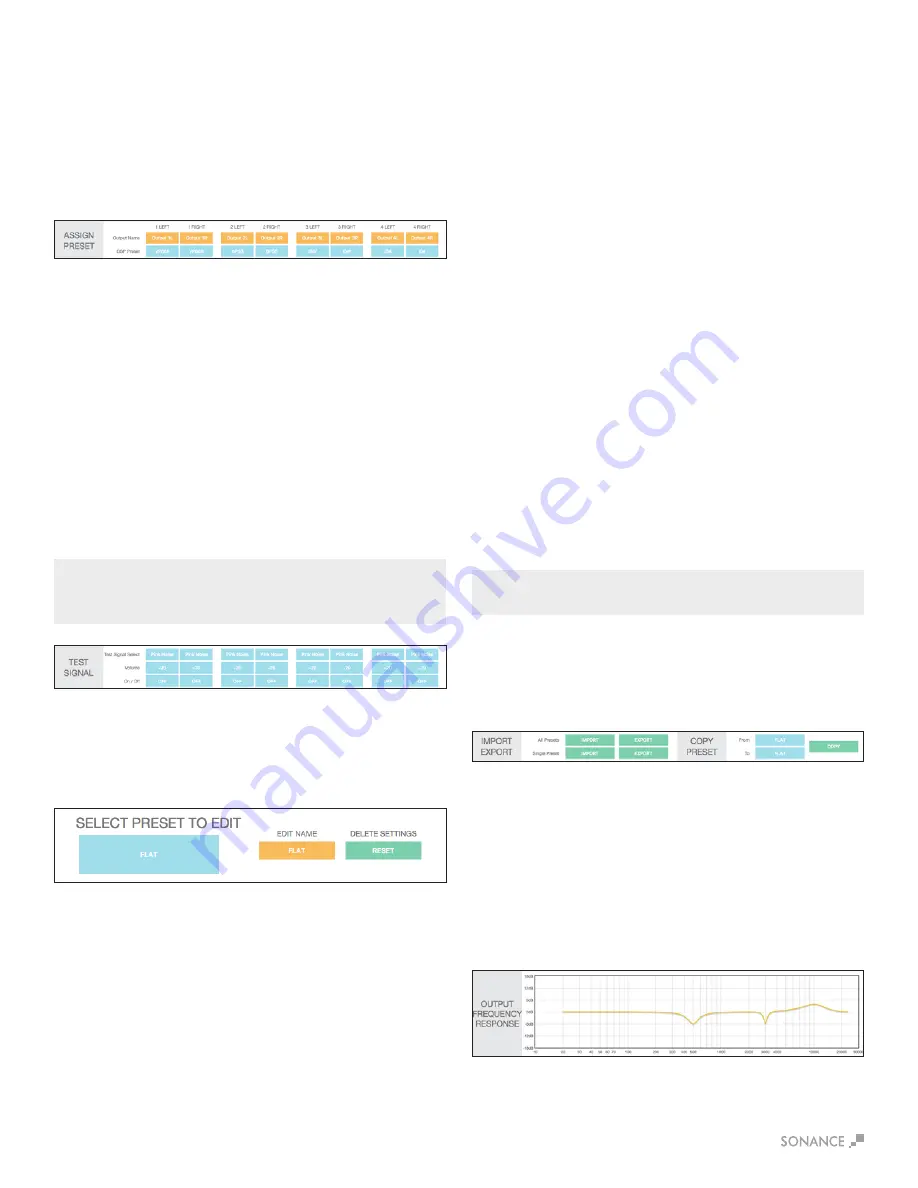
Output Frequency Response

This graph reflects the changes made below.
The EQ image shows EQ4 ON at 500Hz, the Q is set to 3 with a 

-6dB gain, creating a gradual dip in the lower midrange. 
EQ9 shows ON at 3000Hz, the Q is set to 10 with a -6dB gain, 

creating a sharp dip in the midrange. 
EQ10 shows ON at 10000Hz, the Q is set to 1 with a +4dB gain, 

creating a very gradual slope in the high frequencies.

NOTE: THE PINK NOISE GENERATOR IS AFTER THE AUDIO SENSORY 

CIRCUIT SO THE AMP WILL GO TO SLEEP DEPENDING ON THE AUTO ON 

MODE SELECTED. IF THE PINK NOISE STOPS, POWER CYCLE THE AMP.

Summary of Contents for DSP 2-150 MKII

Page 1: ...ET CALIBRE DU FUSIBLE AC 100 120V 60Hz AC 220 240V 50Hz CAUTION RISK OF ELECTRIC SHOCK DO NOT OPEN AVIS RISQUE DE CHOC ELECTRIQUE NE PAS OUVRIR Sonance DSP2 750 MKII Amplifier Rear Panel 4 2 2018 Die Line Do Not Print Prints W hite 1L 1R DSP 2 750 MKII 1 R 1 L 2 R 2 L IN IN OUT OUT DSP 2 750 MKII S N 1 RIGHT 1 LEFT _ _ _ BRIDGE 4 Ω MIN _ _ VOLTAGE TRIGGER 3 30 volts AC DC IN OUT IN OUT IR CONTROL ...

Page 2: ...ont Panel Rear Panel 4 Amplifier Power Requirements 6 Connections Volume Level Controls 7 Protection Circuitry LEDs Stacking 8 Network Connection Instructions 9 Basic Setup 9 Advanced Setup 10 Specifications 15 Appendix A B 16 Troubleshooting 17 Warranty 19 1 ...

Page 3: ...ition does not interfere with its proper ventilation For example the unit should not be situated on a bed sofa rug or similar surface that may block the ventilation openings or be placed in a built in installation such as a bookcase or cabinet that may impede the flow of air through the ventilation openings 9 Heat The unit should be situated away from heat sources such as radiators heat registers ...

Page 4: ...uitable cabinet fans Never place any object on or against the amplifier Never operate the amplifier on a carpeted surface as this will compromise ventilation When the amplifier is installed in any cabinet the front or back must be open during operation Alternately install fans in the cabinet to assure continuous ventilation Sonance DSP2 750 MKII Amplifier Rear Panel 4 2 2018 Die Line Do Not Print ...

Page 5: ...WITH SAME TYPE AND RATING OF FUSE ATTENTION REMPLACER UNIQUEMENT AVEC LE MEME TYPE ET CALIBRE DU FUSIBLE AC 100 120V 60Hz AC 220 240V 50Hz CAUTION RISK OF ELECTRIC SHOCK DO NOT OPEN AVIS RISQUE DE CHOC ELECTRIQUE NE PAS OUVRIR Sonance DSP2 750 MKII Amplifier Rear Panel 4 2 2018 Die Line Do Not Print Prints W hite 1L 1R DSP 2 750 MKII 1 R 1 L 2 R 2 L IN IN OUT OUT DSP 2 750 MKII S N 1 RIGHT 1 LEFT ...

Page 6: ...ROTECTION AGAINST FIRE REPLACE THE FUSE WITH ONLY THE SAME TYPE AND RATING Power Cord The Sonamp DSP 2 750 MKII features a removable power cord Plug the female end of the power cord into the Power Cord Connector on the amplifier rear panel and plug the male end into a grounded wall socket DO NOT plug the amplifier s power cord into a convenience outlet on any other audio or video component If you ...

Page 7: ...OUTLET UNTIL ALL SYSTEM CONNECTIONS HAVE BEEN MADE AND VERIFIED Source Connections Selection DSP 2 150 MKII There are two options when connecting audio inputs to the DSP 2 150 MKII amplifier see Figure 8 Primary Line Inputs 1 L 1 R Use these inputs for primary audio source Secondary Line Inputs 2 L 2 R Use these inputs for a secondary audio source paging or a doorbell Amplifiers Power Requirements...

Page 8: ...IN CLASS 2 WIRING 2 LEFT 2 RIGHT BRIDGE CLASS 2 WIRING 3 LEFT 3 RIGHT BRIDGE CLASS 2 WIRING 4 LEFT BRIDGE CLASS 2 WIRI 8 Ω MIN 8 Ω MIN 8 Ω MIN Figure 14 SonARC Page In Out Settings Output Volume Speaker Connections For the best sound you should use premium speaker wire that complies with fire rating codes Be sure to check local codes governing wire that may be installed within walls or ceilings So...

Page 9: ...n LEDs will turn red The output will remain muted until the fault is cleared Check the rear panel block connector for shorted wire strands or reduce the number of speakers connected in parallel to the amplifier outputs Sonance amplifiers are rated for a 4 ohm load or higher such as two pair of eight ohm speakers Rack Ear Installation DSP 2 750 MKII The DSP 2 750 MKII ships with two rack ears Unscr...

Page 10: ...eless SonARC Homepage Setup Options Your SonARC Homepage will have two options for setup Basic Setup and Advanced Setup Amplifier name can be entered by the installer Basic Setup Page This page is for basic setup of EQ source and volume To start click on the Basic Setup button DSP Preset Assignment Assign Preset Click on the individual channels to show the drop down menu of preset options Once you...

Page 11: ...the channel will be powering IP Address The second setting in the IP SETUP section is the IP address When DHCP is ON the current IP address will be displayed To change the IP address DHCP must be set to OFF When DHCP is turned off the IP address that the router assigned to the amplifier will still be applied This IP address is a good place to start since it is not being used by another network dev...

Page 12: ...off immediately when the trigger voltage has been removed When a 3 30V AC or DC voltage is sent to the amplifier it will take 6 8 seconds for the amplifier to reproduce audio after going through its power up sequence This mode complies with EU energy saving standards Voltage Green In the Voltage Green Auto On mode the amplifier will power off immediately when the trigger voltage has been removed W...

Page 13: ...lt to left outputs and right inputs to right outputs Source 2 This is a secondary source that based on the mode Source 2 setting described below will either override or mix with Source 1 This input could be used for a doorbell or paging for example Mode Source 2 Off When set to OFF Source 2 has no effect on the operation of the channel Mix When set to MIX Source 1 and Source 2 will be blended toge...

Page 14: ...ebsite 2 Select the location you would like to store the new preset using the SELECT PRESET TO EDIT pull down menu You can save the new preset in any of the open preset locations or you can overwrite an existing preset you do not need 3 Press the green IMPORT button 4 From the pop up menu choose local or internet 5 You will be directed to My Computer Windows or Finder MAC 6 Find select the new pre...

Page 15: ...le control By selecting a start frequency and level you can ramp the bass and or treble up or down The effect of the tilt control is visible in the output frequency response graph Low Tilt High Tilt This setting turns the low and high tilt controls on and off Frequency Enter the start frequency of the tilt in Hz To boost the low frequencies you would typically set the low tilt to 100Hz To boost th...

Page 16: ... channels driven 4 ohms sinewave 1 8 power 270 Watts all channels driven Idle 41 Watts IP or IR standby 1 6 Watts Standby 0 4 Watts Power Consumption 220V AC 8 ohms sinewave full power 1220 Watts all channels driven 4 ohms sinewave full power 1720 Watts all channels driven 8 ohms sinewave 1 8 power 200 Watts all channels driven 4 ohms sinewave 1 8 power 257 Watts all channels driven Idle 38 Watts ...

Page 17: ...reen LED Signal is present 1 0mv on channel Blinking Green Signal is going above and below the active level or between songs Blinking Red The channel is being over driven Solid Red The amp is in protection mode see page 6 Power Button Blinking Light Amp temperature exceeds the design maximum LED s Blinking Red Step 1 Turn amplifier off Step 2 With light pressure adjust 1L Volume Control full count...

Page 18: ...ll unavailable contact Dana Innovations Technical Support No IP Control Ethernet connection is made but IP control is not responding Cause Faulty ethernet cable Solutions Check the rear panel network LEDs on the input card are flashing to indicate network connectivity If these LEDs are not active replace the Ethernet cable If the network LEDs are active but the DSP amp will not respond perform the...

Page 19: ...nctioning channel Replace the affected channel s interconnect cable and retest Test source on another audio system to confirm channel outputs are functioning Cause Speaker wire leading out to the channel is loose disconnected or faulty Solutions Verify proper connection of the speaker wire at amp end and speaker end If the channel is still inoperative disconnect the speaker wire from the non funct...

Page 20: ...OR CONSEQUENTIAL INCIDENTAL ECONOMIC PROPERTY BODILY INJURY OR PERSONAL INJURY DAMAGES ARISING FROM THE PRODUCT ANY BREACH OF THIS WARRANTY OR OTHERWISE This warranty statement gives you specific legal rights and you may have other rights which vary from state to state Some states do not allow the exclusion of implied warranties or limitations of remedies so the above exclusions and limitations ma...

Reviews: