AkitikA GT-108, Assembly Manual
The AkitikA GT-108 speaker assembly manual is now available for free download from manualshive.com. This comprehensive manual provides detailed instructions on how to easily assemble and set up your GT-108 speaker for optimal performance. Download your copy today and enjoy the perfect sound experience.
Share
Download


Reviews:
No comments
Related manuals for GT-108

ZEN CAN
Brand: ifi Pages: 21

VAIL CAST
Brand: Vanguard Dynamics Pages: 3

PA-1414MX
Brand: Monacor Pages: 20

CRX-626MP3
Brand: SKP Pro Audio Pages: 12

156416
Brand: Teac Pages: 96

H-SA754
Brand: Hyundai Pages: 17

Zamp v.3
Brand: Parasound Pages: 14

POWER 400 - POWER 400 AMPLIFIER
Brand: Jensen Pages: 44

M-DSPA.402
Brand: Macrom Pages: 17

AFD100 Slash Signature
Brand: Marshall Amplification Pages: 6

PMU-360N
Brand: Inter-m Pages: 32

Cinenova 7
Brand: EarthQuake Pages: 20

112TS
Brand: Bugera Pages: 10

MA 1000.4
Brand: B2 Audio Pages: 6

K-1x
Brand: Ayre Pages: 24

SOUNDPOST SYSTEM
Brand: KURMANN Pages: 2
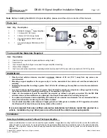
DBA8-19
Brand: INTELIGAIN Pages: 3

CITATION IV
Brand: Harman Kardon Pages: 44


