


21
8.6 Advanced parameters
All the advanced parameters, due to their importance, are already set during initial setup (
cap. 6.2 Initial Configuration)
.
However, it is always possible to modify individual parameters or modify the password 2:
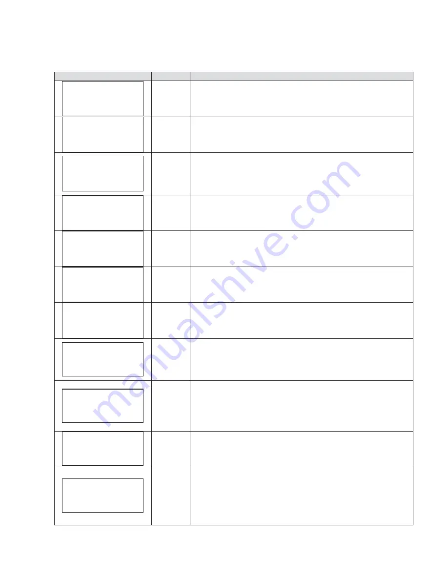
Parameters
Default
Description
XXX
Open circuit voltage of PV strings. Please refer to PV panels datasheet.
XXX
Motor rated voltage (as shown in the motor plate)
Average voltage drop due to the inverter is between 20 V and 30 Vrms
based on load condition.
1%
Refers to the voltage increase during the start up of the motor.
Warning: An excessive value can seriously damage the motor. Contact the
motor manufacturer for further information.
If a single-phase motor is used, a value of 1% is suggested to increase the
starting torque.
XX
Rated current of the motor per it’s nameplate indication increased by 10%.
The voltage drop caused by the inverter leads to higher input current than
nominal. Make sure motor is capable of accepting increased current.
50
Rated frequency of the motor per its nameplate.
50
Maximum frequency of the motor. Note: by reducing the maximum
frequency of the motor, maximum current will be reduced as well.
30
Minimum frequency of the motor. Note: depends on the selected pump
type; for submersible pumps with water filled motors, is not advisable to set
minimum frequency lower than 30 Hz in order to protect the integrity of the
thrust bearings.
4
Ramp-up time to reach the speed required to achieve the set pressure (or
frequency value). Longer times delay the system reaching the preset value
but better protect system components.
Excessively long ramp-up times can create difficulties in VASCO Solar setup,
and can also cause false overload alarms.
4
Ramp-down time to reach zero speed. Longer times keep the system
pressurized, while protecting the system components.
Excessively long ramp-down times can create difficulties in VASCO Solar
setup. Excessively short ramp-down times can cause false overload alarms.
1.5
Time to reach the minimum frequency of the motor and vice versa.
When VASCO Solar
is used to control a water filled submersible motor it’s
important to keep this time at 1 second.
8
Carrier frequency (switching frequency).
It is possible to chose PWM in the range of 2.5 ,4, 6, 8, 10 kHz .
Higher values give a more sinusoidal wave with fewer losses. If long cables
are used (>20 m / >76 ft) (submersible pump) it is recommended to install an
inductive filter between VASCO Solar and the motor (available upon request)
and to set the value of PWM to 2.5 kHz. This reduces the risk of voltage
spikes, which can damage motor and cable insulation.
PWM
f = XX [kHz ]
Ramp f min mot.
t = XX [sec]
Ramp down time
t = XX [sec]
Ramp up time
t = XX [sec]
Min motor freq.
f = XXX [Hz]
Max motor freq.
f = XXX [Hz]
Rated motor freq
f = XXX [Hz]
Rated motor Amp.
I = XX.X [A]
Voltage boost
V = XX [%]
Rated motor Volt.
V = XXX [V]
Open circuit Volt. PV
V = XXX [V]


