background image

Appendix C – Connector Pinouts

Page 53

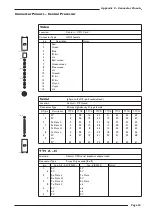
Appendix C: Connector Pinouts – C300HD Console

Note. Connector only fitted if VU meter panel or RTW phasescope specified.

Meter Inputs

(Analogue Circuits)

Location:

Console Connector Panel

Connector Type:

25-way D-type male

pin

Description

Notes:  VU or PPM

Notes:  RTW10830

1

Meter 1 input

+

Left meter

Input 1

14 Meter 1 input

-

2

n/c

15 Meter 2 input

+

Centre meter

Input 2

3

Meter 2 input

-

16 n/c

4

Meter 3 input

+

Right meter

Input 3

17 Meter 3 input

-

5

n/c

18 Meter 4 input

+

LS meter

Input 4

6

Meter 4 input

-

19 n/c

7

Meter 5 input

+

SW meter

Input 5

20 Meter 5 input

-

8

n/c

21 Meter 6 input

+

RS meter

Input 6

9

Meter 6 input

-

22 n/c

10

Meter 7 input

+

unused

Input 7

23 Meter 7 input

-

11

n/c

24 Meter 8 input

+

unused

Input 8

12

Meter 8 input

-

25 n/c

13

n/c

Summary of Contents for C300 HD

Page 1: ...Installation Guide ...

Page 2: ...C300HD Installation Guide ...

Page 3: ...Master Studio System Installation Guide Version 2 0 1 82S6PC3010B Solid State Logic S V I S I N O O U N D ...

Page 4: ... All Rights reserved under International and Pan American Copyright Conventions C100HD C100HD S C200 C300HD Centuri C SB StageBox NetBridge Solid State Logic and SSL are trademarks of Solid State Logic All other product names and trademarks are the property of their respective owners No part of this publication may be reproduced in any form or by any means whether mechanical or electronic without ...

Page 5: ...itching 25 Script Tray option 25 Loudspeaker Shelf option 25 TFT external input option 25 Section 5 Installation 27 Power Connections 27 Console Control 29 Sync 29 I O MicAmp Card 31 I O Analogue Card 31 I O Digital Card 33 I O MADI Card 33 GPI O Card 35 C SB Stagebox Wiring 37 Netbridge 39 Talkback and Oscillator 41 Phasescope and Meter Wiring 43 DAW Midi interface 45 Appendices A Equipment Speci...

Page 6: ...m options Specifications and Physical dimensions Pinouts of standard connectors The information provided by this manual is relevant to all of the versions of the C300HD The aspects of the C300HD which can be customised frame size channel layout meter panel as examples will be fully documented in the Custom Specification information for a specific console The Custom Specification information which ...

Page 7: ...ional practice Installation Instructions Voltage Selection and Fusing Although the majority of SSL equipment uses auto ranging power supplies some sub systems have user selectable voltage inlets Always confirm that the input mains voltage range is set correctly before applying power Always isolate the mains supply before changing the input range setting If it is ever necessary to replace a blown m...

Page 8: ...hemes 1 or 2 LIVE Brown Black NEUTRAL Blue White EARTH Yellow Green Green Mains Isolation and Over Current Protection An external disconnect device switch is required for this equipment which must be installed according to current wiring regulations A detachable power cord if fitted to this equipment is a suitable disconnect device otherwise an approved disconnect switch is required the rating of ...

Page 9: ...on manual may cause harmful interference to radio communications Operation of this equipment in a residential area is likely to cause harmful interference in which case the user will be required to correct the interference at his own expense Instructions for Disposal of WEEE by Users in the European Union The symbol shown here which is on the product or on its packaging indicates that this product...

Page 10: ...ly expected to take from 2 to 4 days depending on system size configuration and options Large systems or consoles split for shipment may require an additional 1 2 days of commissioning time You will be contacted by your local SSL office or agent shortly before delivery to arrange a commissioning date Training Three days of standard operator training are provided with each C300HD system If required...

Page 11: ...ate machine room A 19 equipment rack will need to be provided into which the Centuri Processor can be mounted Note when positioning the rack that cards are inserted into the Centuri Processor from both the front and the rear depending on function Clearance for access to cards must therefore be provided both in front of and behind the rack see page 10 for service clearance diagram A MIDI interface ...

Page 12: ...allation Guide Page 8 1 8 9 16 Centre Section 17 24 25 32 Connector Panels and Power Supplies Mains and audio connectors Console connectors Power supplies Mains panel Audio interface panel Console interface panels ...

Page 13: ...will route towards the rear of the desk The connectors for ancillary functions such as talkback and metering etc are located on a panel at the rear of the Centre Section The mains input power connector will be located on a separate panel This panel is usually positioned in a bay adjacent to the Centre Section nearest to the centre of the console but may vary due to console layout Service Access Ac...

Page 14: ...C300HD Installation Guide Page 10 Centuri Processor Crate side view Showing Card Access C SB Crate side view Showing Card Access Dimensions in mm 592 270 15U 14U 270 462 270 Front Rear Front Rear ...

Page 15: ...sh current present when powering the console can be significant typically ten times the steady current so the use of slow or motor rated fuses circuit breakers is recommended Both the Centuri processor rack and the console control surface can be fitted with backup power supplies for PSU redundancy during live transmissions work The backup supply works independently from the main supply and the con...

Page 16: ...NG GE E G GA AI IN N G GA AI IN N H HM MF F H HF F A AU UT TO O A AU UT TO O A AU UT TO O A AU UT TO O A AU UT TO O A AU UT TO O FREE ASSIGN LINK PROTECT AUTO MODES EXCHANGE MOVE SHOW SET A AU UT TO O A AU UT TO O A AU UT TO O OFF P PA AN N ON A AU UT TO O A AU UT TO O A AU UT TO O OFF P PA AN N ON A AU UT TO O A AU UT TO O A AU UT TO O OFF P PA AN N ON A AU UT TO O A AU UT TO O A AU UT TO O OFF P...

Page 17: ...determined solely by the amount of DSP resource fitted to the processor Each Master Section may optionally be specified with a 6 or 8 channel LCD phase scope and has additional space for mechanical VU meters a 6 off 5 1 VU meter panel is available to order as a standard option Alternatively a range of custom meter configurations is possible these should be detailed at the time of order The standar...

Page 18: ...r Digital Access to CPU card Console interface card GPI O card Routing Link card fitted with 2 Fibre Link ports I O Cards Analogue Digital or Mic DAW Midi interface panel special order only NB Cards shown are an example Configuration will vary according to specification 3 3V 5V 5 5V 15V 15V O I 3 3V 5V 5 5V 15V 15V O I 5V 3V3 FLAG 1 FLAG 12 RESET Solid State Logic O X F O R D E N G L A N D 5V 3V3 ...

Page 19: ...ws Slots 1 4 Channel DSP cards Slot 5 Always fitted with a master DSP card for mix processing Slot 6 Optional 2nd master DSP card for enhanced 2Fs bus capacity and processing Slots 7 10 Can be a combination of additional DSP cards and or micamp cards digital or MADI cards to special order only Slot 11 Always blank There rear of the processor has space for 12 plug in cards Note that these slots are...

Page 20: ... O R D E N G L A N D DSP CARD MACHINE CONTROL TIME CODE CONTROL SURFACE 1 CONTROL SURFACE 2 CONTROL SURFACE 3 IN 1 OUT 1 IN 2 OUT 2 W CLK IN 3 OUT 3 IN 4 OUT 4 W CLK 909XN CPU Card Console Interface Card Routing Link Card Shown equipped with two Madi fibre ports 5V 1 6 7 12 SPLIT OUTPUTS MIC IN 1 12 Microphone Input Card DSP Card ...

Page 21: ...ri is always fitted with a Routing Link card It must be fitted to the rear card cage in position 5 This card has two functions The first is an internal function to manage the audio routing across the system s backplane The second is to provide an interface for up to four optional MADI fibre ports These ports provide access to remote SSL Stageboxes or can be used as synchronous MADI I O ports Each ...

Page 22: ...IN OUT AES SYNC Tx Rx Tx Rx LOCK A LOCK B MADI A1 A1 ANALOGUE IN 1 24 ANALOGUE OUT 1 24 9 16 1 8 25 32 17 24 AES EBU IN 9 16 1 8 25 32 17 24 AES EBU OUT IN OUT WORD SYNC IN OUT AES SYNC Tx Rx Tx Rx LOCK A LOCK B MADI Digital I O Card MADI I O Card Copper version MADI I O Card Fibre version GPI I O Card Analogue I O Card ...

Page 23: ...tion The 64 32 Channel mode will accept 0 1 variations in sample frequency Only synchronous 2Fs MADI signals with legacy framing are supported and anyWord Clock or AES sync signal must be disconnected from the MADI card or the audio will be muted BothWord Clock and unbalancedAES 3id sync inputs and outputs are provided If the incoming MADI signal is synchronous i e derived from a device locked to ...

Page 24: ...SIG OVER LOAD SELECT 48V SIG OVER LOAD SELECT 48V SIG OVER LOAD SELECT 48V SIG OVER LOAD SELECT PUSH PUSH PUSH PUSH PUSH PUSH PUSH PUSH 48V SIG OVER LOAD SELECT 48V SIG OVER LOAD SELECT 48V SIG OVER LOAD SELECT 48V SIG OVER LOAD SELECT 48V SIG OVER LOAD SELECT 48V SIG OVER LOAD SELECT 48V SIG OVER LOAD SELECT 48V SIG OVER LOAD SELECT PUSH PUSH PUSH PUSH PUSH PUSH PUSH PUSH 48V SIG OVER LOAD SELECT...

Page 25: ...re available on 25 way D type male connectors Remote stageboxes are connected to the Centuri core by using duplex fibre optic cable 1 for the Madi audio data referred to as a GLink in the software and a separate Ethernet cable 2 for the control functions gain pad filter etc The audio fibre links to a stagebox can be duplicated thus creating audio redundancy for critical or on air reliability The n...

Page 26: ...gland FUSE risk of fire use same type and rating IEC 127 250V 250V Ratings AC 50 60Hz Volts Amps 626755X4 90 125 1 2 0 9 195 255 0 6 0 5 10A T 5A T DATE INITIALS TESTED NetBridge Front View NetBridge Rear View NetBridge PSU Voltage Selection Voltage select switch shown in the 230V position Voltage select switch shown in the 115V position 230 230 115 ...

Page 27: ...oad a console template to a secure website edit the configuration offline and then reload their profile prior to the production saving valuable setup time Parameters available for offline configuration include fader strip allocations channel names and type bus routing assignments processing order output options and fader grouping setup NetBridge requires access to the facility s internet service T...

Page 28: ...S ETH CTRL ETHER 2 VID 1 VID 2 ETHER 1 ETHER 3 ETHER 4 MIC GN CTRL 3 CTRL 2 CTRL 1 Location of Console Connectors Location of Audio Connectors Console control Analogue meter inputs option USB soft key data Softkey data in Phasescope diagnostics option Phasescope digital input option TB mic in TB out USB hub in USB kbd bitpad data Console Ethernet hub USB hub out Centuri SXGA Alt SXGA Unused ...

Page 29: ...ported Keyboard short commands supplementing the existing MIDI DAW control offered on C300 The standard connector panel includes a two port USB hub to simplify installation by allowing the simulated USB keyboard data to be merged with the commands from the physical keyboard connected to the console with a single USB link to the PC or MAC running the DAW software Two USB A B cables are supplied wit...

Page 30: ...POWER INDICATORS REMOTE POWER INDICATORS PSU 1 PSU 2 SERIAL 1 8 TERMINAL SERIAL 9 230 SSL TCP IP Model Serial No Solid State Logic Oxford England FUSE risk of fire use same type and rating IEC 127 250V 250V Ratings AC 50 60Hz Volts Amps 626755X4 90 125 1 2 0 9 195 255 0 6 0 5 10A T 5A T DATE INITIALS TESTED Chassis Bolt Chassis Bolt ...

Page 31: ...UST NOT BE FROM DIFFERENT PHASES OF A 3 PHASE SUPPLY b Connect the Centuri s IEC lead s to appropriate mains supply outlet s If a redundant PSU module is specified refer to the notes above for suitable supply provision The Centuri crate is also fitted with auto ranging power supplies which will accept mains voltages which range from 100 to 240V without adjustment c If specified do not connect a so...

Page 32: ... SYNC VIDEO 3 VIDEO 2 VIDEO 1 ETHERNET SERIAL CTRL USB IN1 USB IN2 K BOARD USB OUT VU MTRS ETH CTRL ETHER 2 VID 1 VID 2 ETHER 1 ETHER 3 ETHER 4 MIC GN CTRL 3 CTRL 2 CTRL 1 Control Surface Wiring Block Diagram CPU Card Control Card Console Connector Panel Front Panel cables x 2 XGA video lead RJ45 Ethernet lead Sync connector ...

Page 33: ...ge The console has a built in 4 way Ethernet repeater Connect the Ethernet lead between the Centuri CPU card and any of the four Ether sockets beneath the console If Netbridge is specified then a second RJ45 Ethernet lead will be supplied with the system This lead is connected between the console and the SSL Network connector on the NetBridge rear panel c Video Cable There are three video outputs ...

Page 34: ...S MIC IN 1 12 A1 A1 ANALOGUE IN 1 24 ANALOGUE OUT 1 24 Micamp Input Card Analogue I O Card Split Output Connectors 25 pin D type female Microphone input Connector Varicon 56 way female Analogue Input Connector DL96 female Analogue Output Connector DL96 female ...

Page 35: ...SL ref 904 The Analogue Card provides 24 circuits of electronically balanced input and output These circuits are accessed via Canon DL 96 way female connectors mating connectors are available to order Refer to Appendix C for the connector pinouts As is the case for the MicAmp cards added subsequently should be placed to the left of existing cards The default line up level for analogue I O is 0dBFS...

Page 36: ... EBU OUT IN OUT WORD SYNC IN OUT AES SYNC Tx Rx Tx Rx LOCK A LOCK B MADI Digital I O Card MADI I O Card Copper version AES EBU Output Connectors 25 pin D type female AES EBU Input Connectors 25 pin D type female MADI Link A BNC 75π MADI Link B BNC 75π MADI Word Sync BNC 75π AES Sync BNC 75π ...

Page 37: ...hese looms should not be extended beyond 1m as the signals are unbalanced and signal quality may be reduced As in the case of the Analogue I O cards added subsequently should be placed to the left of existing cards When assigning digital output channels as insert sends the routing system will automatically assign the same input channel number as the corresponding return It is therefore necessary t...

Page 38: ...Page 34 C300HD Installation Guide GPI I O Card IN OUT 1 12 13 24 25 36 37 48 49 60 1 12 13 24 25 36 37 48 49 60 GPI GPI input Connectors 25 way D type Male GPI output Connectors 25 way D type Female ...

Page 39: ...nd output signals can be either latching or momentary This setting is individually assigned in software via the touch screen When set to momentary the input signal duration must be greater than 50mS When used for track arming and tally the tally must return to the same number input as the output signal ie the tally for GPI Out 1 will be on GPI In 1 GPI Outputs The switch closure is by DIL relay Co...

Page 40: ...Network RJ45 SC Fibre i f 1a control link SC Fibre i f 1b SC Fibre i f 1b Page 36 C300HD Installation Guide IN 1 OUT 1 IN 2 OUT 2 W CLK IN 3 OUT 3 IN 4 OUT 4 W CLK 909XN Centuri Link Card Fitted with two redundant Madi interfaces Connection with UTP control link 100m max Duplex fibre SC Ethernet RJ45 Redundant connection with fibre control link 100m Stagebox CPU Card TERMINAL NETWORK CH1 CH2 CH3 C...

Page 41: ...er fibre cables and or ruggedised OB cable using adaptor panels patch panels may be available to order SSL is able to suggest a range of fibre solutions although the facility may prefer to provide its own fibre installation Details of fibre installation options should be discussed with SSL s Project Engineering Department prior to the time of order When Stageboxes are specified it is recommended t...

Page 42: ...A AA AA AA AA AA AA AA AA AA AA AA AA AA AA AA AA AA AA AA AA AA AA AA AA AA AA AA AA AA AA AA AA AA AA AA AA AA AA AA AA AA AA AA AA AA AA AA AA E T H E R N E T V ID E O 3 V ID E O 2 S Y N C V ID E O 1 9 6 0 X A S E R IA L RS232 Diagnostics Cable RS232 Terminal Cable SSL Network TCP IP Network Internal Network External Network Maintenance Access NetBridge Installation Operational Access TCP IP ne...

Page 43: ...l which must be passed through any firewall and redirected as required although this is unlikely to cause any security concerns as it has 128bit Secure Socket Layer encryption For file transfer between the console and the CFS the user must be logged in at the console itself For file transfer between the CFS and another computer eg authorised freelance engineer or SSL support staff the user may log...

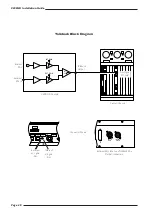
Page 44: ... B MIC IN TALKBACK OUTPUT PUSH INT GAIN EXT GAIN Internal Mic External Mic in Analogue I O card C300HD Console Talkback Block Diagram External Mic Input and Talkback Mix Output connectors Connector Panels Talkback Output Centuri Chassis External mic gain trim Internal mic gain trim ...

Page 45: ...independently adjusted Access to the trim controls is from beneath the console on the console interface panel The external mic input is via a 3 pin XLR female labelled Ext T B Mic In The mixed T B output is via a 3 pin XLR Male labelled Talkback Output Oscillator Connections The C300HD includes an inbuilt software oscillator capable of generating a range of sinusoidal frequencies as well as pink n...

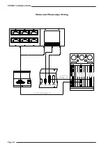
Page 46: ... 5 7 10 2 0 1 0 1 2 3 VU VU 2 3 5 7 10 2 0 1 0 1 2 3 VU VU 2 3 5 7 10 2 0 1 0 1 2 3 VU VU 2 3 5 7 10 2 0 1 0 1 2 3 VU VU 2 3 5 7 10 2 0 1 0 1 2 3 VU VU VU MTRS ETH CTRL VIDEO IN MSD DIAG PHASE SCOPE REMOTE POWER IN Analogue I O card Digital I O card 3 or 4 off AES EBU ccts 6 or 8 off analogue ccts ...

Page 47: ...need to be run between the Centuri and the Console Both balanced analogue and 110Ω digital cables may be necessary depending on configuration These cables are not supplied by SSL The MSD600C 5 1 phasescope has inputs for 6 digital signals 3 AES EBU pairs plus a serial diagnostic port The RTW 10830 has eight digital input signals eight digital output signals eight analogue input signals plus a remo...

Page 48: ...e EXPANSION TIME 1 2 3 4 5 6 7 8 9 10 11 12 MIDI IN MIDI OUT MIDI IN MIDI OUT CODE DAW MIDI Interface Panel Timecode output MMC option input only Midi 9 11 Midi 5 8 Midi 1 4 Workstation 1 Master Workstation 2 Slave Workstation 3 Slave ...

Page 49: ...ons The maximum number of ports that can be utilised for control is workstation specific for example the DigiDesign Pro Tools is limited to a maximum of 4 ports Please consult the DAW documentation to determine how many physical ports can be used In most cases the DAW software supports banking so that the physical console control channels can be paged through all the available tracks in a workstat...

Page 50: ...lient Sheet Revision Drawn by Date 21 02 08 GC Footprint C300 32 Channels Standard Configuration Proposal 0 1 Solid State Logic S V I S I N O O U N D 32 channel footprint drawing Refer to table opposite when calculating frame configurations Alternatively contact SSL Project Engineering at projeng solidstatelogic com ...

Page 51: ... subtract 70 W approximately Voltage Range 100 240 V AC only 10 Current 48ch Maximum over voltage range 10 3 4 3 A Power Factor 0 95 approximately Fusing No user accessible fuses Noise Fanless Connectors Power in main backup Harting Modular 3 pin Network RJ45 100 baseT Control Surface 3M MDR high density 50 way female Video in 1 and 2 HD15 female Trackball out USB B female External USB in USB A fe...

Page 52: ... Power Factor 0 95 approximately Fusing Thermal current trip No fuses 16 A each input Noise 75 dB A approximately Connectors Power in 1 and 2 IEC male Network RJ45 100 baseT Sync in BNC 75Ω analogue video Video out 1 2 and 3 HD15 female Serial 62 way HD D type female 9 way breakout lead supplied Control Surface 3M MDR high density 50 way female Machine Control 25 way D type male Timecode 25 way D ...

Page 53: ...tion 32 DSP no I O 45 W maximum Voltage Switch selectable 115 or 230 V AC only Current At 115V input 0 5 A At 230V input 0 2 A Fusing No external fuses Noise 50 dB A approximately Connectors Power in IEC male Network TCP IP RJ45 Network SSL RJ45 Terminal 9 way D type male Serial 62 way HD D type female 9 way breakout lead supplied Netbridge must be supported on rack shelves Do not rely on the rack...

Page 54: ...ables Weight Rack with single PSU unit 19 kg Each Mic input or Line output card 1 7 kg Additional PSU module 5 8 kg Heat Dissipation 380 W maximum with 48ch fitted Voltage Range 100 240 V AC only Current At voltage range 10 0 3 9 A maximum with 48ch fitted Fusing 6 3 T A 1 25 time delay Noise Fanless Connectors Mains supply in IEC male Mains supply output x2 IEC female 6A max total Network SSL RJ4...

Page 55: ...5 6 7 8 1 2 3 4 5 6 7 8 S So oc ck ke et t D DL L 9 96 6 P Piin n V Va ar riic co on n 5 56 6 p piin n Dimensions 29mm x 69mm Dimensions 22mm x 67mm A E R a k u DD L W e h p z KK B F S b l v EE M X r AA LL C H T w FF N Y s BB MM D J U c m x HH P Z f j t CC NN K V d n y JJ A E R a k u DD L W e h p z KK B F S b l v EE M X r AA LL C H T w FF N Y s BB MM D J U c m x HH P Z f j t CC NN K V d n y JJ 70 ...

Page 56: ...cket Plug Socket 1 5 15 6 10 11 Socket Viewed from wiring side Pin 1 LIVE Pin 2 n c Pin 3 NEUTRAL Earth contact is via Earth pin in the housing frame Note The inserts utilise crimped pins which are not removable Part SSL Part Number 3 way socket housing 32VAK3DC 40A Contact 32VAQXEX Plug Socket 1 2 3 1 2 3 XLR 3 Pin Dimensions 19 x 60mm approx Cable Dia 8 12mm typical Pinout for balanced audio Pin...

Page 57: ...M Notes RTW10830 1 Meter 1 input Left meter Input 1 14 Meter 1 input 2 n c 15 Meter 2 input Centre meter Input 2 3 Meter 2 input 16 n c 4 Meter 3 input Right meter Input 3 17 Meter 3 input 5 n c 18 Meter 4 input LS meter Input 4 6 Meter 4 input 19 n c 7 Meter 5 input SW meter Input 5 20 Meter 5 input 8 n c 21 Meter 6 input RS meter Input 6 9 Meter 6 input 22 n c 10 Meter 7 input unused Input 7 23 ...

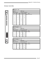
Page 58: ... 8 n c 21 Circuit 6 unused AES EBU in 5 6 9 Circuit 6 22 n c 10 Circuit 7 unused AES EBU in 3 4 23 Circuit 7 11 n c 24 Circuit 8 unused AES EBU in 1 2 12 Circuit 8 25 n c 13 n c Phase Scope Diagnostics and Control Location Audio connector panel Connector Type 9 way D type female pin Notes MSD600 Notes RTW10830 1 Chassis Switch common 6 n c Mode 2 Rx Data Select 7 n c Memo 3 Tx Data Gain 8 n c Rese...

Page 59: ...or Type 62 way high density D type female D9 pin Description TTY A TTY B TTY C TTY D TTY E TTY F TTY G TTY H 1 0V 7 28 14 52 21 42 35 59 6 0V 5 26 12 50 19 40 33 57 2 Rx Data L 2 23 9 47 16 37 30 54 7 Rx Data H 3 24 10 48 17 38 31 55 3 Tx Data H 2 22 8 46 15 36 29 53 8 Tx Data L 4 25 11 49 18 39 32 56 4 0V 6 27 13 51 20 41 34 58 9 n c 5 0V 43 45 44 44 62 61 60 61 TTY A H Location Centuri CPU seria...

Page 60: ...ut 4 13 out 4 gnd Machine Control Location Centuri Console interface card Connector Type 25 way D type female pin Description Notes 1 n c 14 n c 2 Tally common Tally voltage can be AC or DC 4V to 30V 15 Switch common 3 Rewind switch 16 Rewind tally 4 Forward switch 17 Forward tally 5 Stop switch 18 Stop tally 6 Play switch 19 Play tally 7 Skip back switch 20 Skip back tally 8 Record switch 21 Reco...

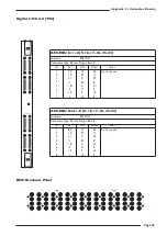
Page 61: ...3 21 9 22 4 7 20 8 5 18 6 19 6 4 17 5 Split Outputs 7 12 Location 908 Micamp Connector Type 25 way D type female Cct Hot Cold Screen Notes 7 24 12 25 Pin 13 unused 8 10 23 11 9 21 9 22 10 7 20 8 11 18 6 19 12 4 17 5 MIC In 1 12 Location 908 Micamp Connector Type Varicon 56 way female Cct Hot Cold Screen Notes 1 D K P All other pins unused 2 C J N 3 A E L 4 B F M 5 V Z d 6 U Y c 7 R W a 8 S X b 9 n...

Page 62: ...3 C3 4 A4 B4 C4 5 A5 B5 C5 6 A6 B6 C6 7 A7 B7 C7 8 A8 B8 C8 9 D1 E1 F1 10 D2 E2 F2 11 D3 E3 G1 12 D4 E4 G2 13 D5 E5 G7 14 D6 E6 G8 15 D7 E7 F7 16 D8 E8 F8 17 L1 K1 J1 18 L2 K2 J2 19 L3 K3 H1 20 L4 K4 H2 21 L5 K5 H7 22 L6 K6 H8 23 L7 K7 J7 24 L8 K8 J8 C300HD Installation Guide Page 58 Analogue I O Card 904 A1 A1 ANALOGUE IN 1 24 ANALOGUE OUT 1 24 ...

Page 63: ...2 1 9 2 0 2 7 2 8 5 6 13 1 4 2 1 2 2 2 9 3 0 7 8 1 5 1 6 2 3 2 4 3 1 3 2 IN OUT AES EBU In 1 8 9 16 17 24 25 32 Location 902 DIO Connector Type 25 way D type female Cct Hot Cold Screen Notes 1 24 12 25 Pin 13 unused 2 10 23 11 3 21 9 22 4 7 20 8 5 18 6 19 6 4 17 5 7 15 3 16 8 1 14 2 AES EBU Out 1 8 9 16 17 24 25 32 Location 902 DIO Connector Type 25 way D type female Cct Hot Cold Screen Notes 1 24...

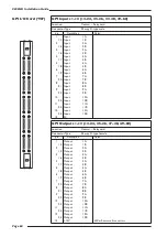
Page 64: ...t 11B 12 Output 12A 25 Output 12B 13 15V 450mA across all connectors C300HD Installation Guide Page 60 GPI I O Card 907 IN OUT 1 12 13 24 25 36 37 48 49 60 1 12 13 24 25 36 37 48 49 60 GPI GPI Inputs 1 12 13 24 25 36 37 48 49 60 Location Centuri Relay card Connector Type 25 way D type male pin Description Notes 1 Input 1A 14 Input 1B 2 Input 2A 15 Input 2B 3 Input 3A 16 Input 3B 4 Input 4A 17 Inpu...

Page 65: ...1 7 CPU Card Console 1 5 6 9 5 1 9 6 NetBridge Diagnostic Cable Serial 1 8 RS232 Location Netbridge Rear panel Connector Type 9 way D type male pin Description Notes 1 Chassis 6 n c 2 Rx Data 7 n c 3 Tx Data 8 n c 4 n c 9 n c 5 0V Terminal RS232 Location Netbridge Rear panel Connector Type 9 way D type male pin Description Notes 1 DCD Data Carrier Detect 6 DSR Data Set Ready 2 Rx Data 7 RTS Reques...

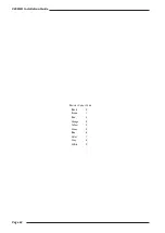
Page 66: ...C300HD Installation Guide Page 62 Resistor Colour Code Black 0 Brown 1 Red 2 Orange 3 Yellow 4 Green 5 Blue 6 Violet 7 Grey 8 White 9 ...

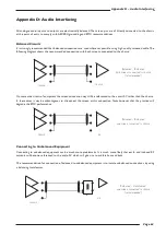
Page 67: ...the circuit 0V rather than the chassis In these cases it may be advantageous to disconnect the screen at this connection Note however that this practice will degrade the EMC performance Connecting to Unbalanced Equipment Connecting to unbalanced equipment can be much more problematic It is much more likely that earth and induced RF currents will become referenced to the audio 0V which will give ri...

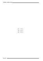
Page 68: ...C300HD Installation Guide Page 64 1 inch 25 4mm exactly 1m 3 3 roughly 1 mile 1 600m roughly 1Kg 2 2 Pounds roughly ...

Page 69: ...Relative Humidity Operating 20 to 80 Non operating 5 to 90 Max wet bulb 29 Deg C non condensing Vibration Operating 0 2 G 3 100Hz Non operating power off 0 4 G 3 100Hz Shock Operating 2 G 10mSec Max Non operating 10 G 10mSec Max Altitude Operating 0 to 3000 m above sea level Non operating 0 to 12000 m Appendix E Environmental Specification ...

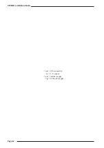
Page 70: ...C300HD Installation Guide Page 66 4dBu 1 229V rms 0dBu 0 775V rms 6dBu 0 388V rms ...

Page 71: ... just below the rear heatsink Microphone cables must not obstruct the air intake To help ensure this a cable guide is provided down the sides of the rack Design Requirements for a Flightcase If a Stagebox is to be installed into a flight case the following requirements in addition to those above must be met to ensure adequate passive cooling otherwise user must install a forced ventilation kit opt...

Page 72: ...ontrols can send true jog and shuttle commands to 9 pin controlled devices or can control the desk s built in virtual machine in comparable modes Primary Machine Control Options Sony 9 Pin controls machines using the Sony P2 RS422 remote protocol including track arming support This can be used with video machines DAT and MDM recorders which support 9 pin control as well as disk based workstations ...

Page 73: ...r synchronous operation Serial slave machines will not follow transport commands originated on the Master machine in this mode The second mode can be used to interface the desk to an external machine controller VPR3 Alternative RS422 9 pin control protocol used primarily with the legacy Timeline Lynx I II synchronisers for parallel and bi phase machine control Also supports the JSK bi phase contro...

Page 74: ...C300HD Installation Guide Page 70 volume of a sphere 4 π r 3 3 ...

Page 75: ...cables 25 way D type to 9 way D type RS232 10m 66C60002 RJ45 to 25 way D type RS232 10m 66C67206 9 way D type to 9 way D type RS422 10m 66C60007 Network Cables Ethernet RJ45 to RJ45 10baseT 0 5m pin pin 66C67207 Ethernet RJ45 to RJ45 10baseT 1m pin pin 66C67210 Ethernet RJ45 to RJ45 10baseT 2m pin pin 66C67220 Ethernet RJ45 to RJ45 10baseT 5m pin pin 66C67250 Ethernet RJ45 to RJ45 10baseT 10m pin ...

Page 76: ...C300HD Installation Guide Page 72 Notes ...

Reviews: