


Installation Wiring
Section 5
Page 35
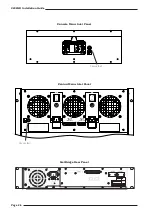
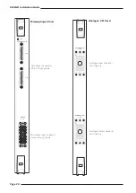
I/O – GPI I/O (SSL ref. 907XA)
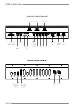
The GPI I/O Card contains 60 circuits of opto-isolated input and 60 circuits of relay-closure output. Inputs are accessed
by 25-pin D-type male connectors and outputs by 25-pin D-type female connectors; mating connector kits are available to
order.
Both the input and output circuits are fully isolated from the processor electronics. On all output connectors, there is a
protected source of +15V available and a 0V reference is available on each input connector.
The input and output signals can be either latching or momentary. This setting is individually assigned in software via the
touch screen. When set to momentary the input signal duration must be greater than 50mS.
When used for track arming and tally, the tally must return to the same number input as the output signal, (ie. the tally
for GPI Out 1 will be on GPI In 1).
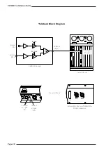
GPI Outputs
The switch closure is by DIL relay. Contact rating is 100Vdc, 125Vac, 100mA max. Do not use the output contacts to
directly switch capacitive or reactive loads, always use an external relay with a suitable contact rating.
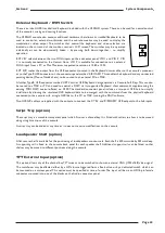
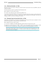
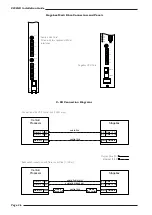
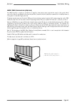
GPI Inputs
The signal input requires AC or DC voltage between 4V and 30V. The current drawn is approximately 10mA.
GPI in
Input A
Input B
Contact A
Contact B