PRODUCT MANUAL
8-Zone RGB Remote Control
8-Z
one R
GB R
emot
e C
on
tr
ol
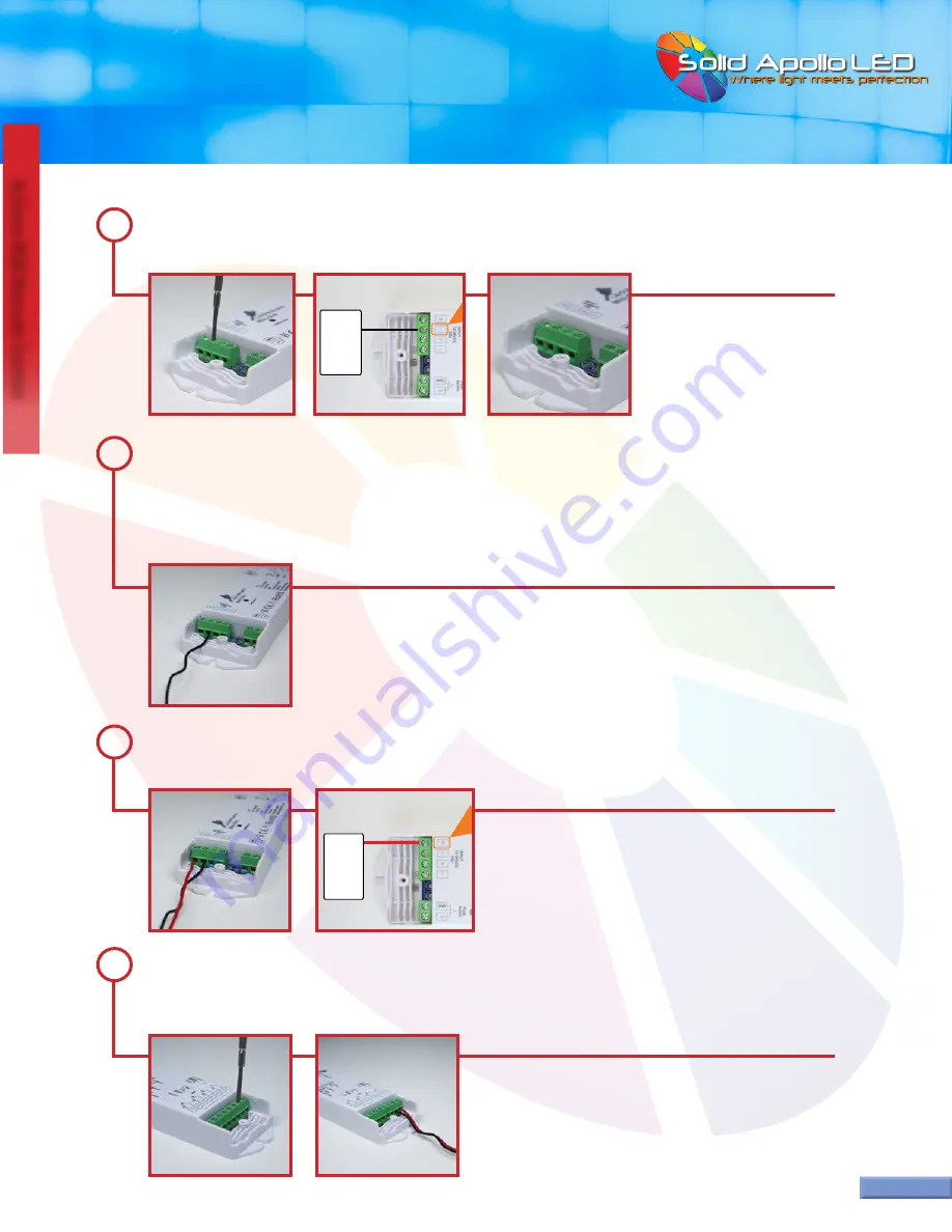
On the left green wiring slot block for the power supply, use the Philips Screwdriver to rotate the negative wiring screw
counter clockwise to open the wiring slot located below the screw. The screw will not come out.
3
Take the negative wire and insert the exposed metal end into the negative wiring slot located below the screw. Place
the wire inside until the wire stops against the wall inside the negative wiring slot. Take the Philips Screwdriver and
turn the negative wiring screw clockwise until the screw is snug. The negative wire has now been secured to the receiver
and should not come out. If it does come out, repeat from step two, and place the exposed metal wire further into the
negative wiring slot.
4
Repeat steps two through four for the positive wire from the power supply. The positive wire will go into the positive
wiring slot.
5
Page 3
Toll Free: 866.592.3873
Email: [email protected]
www.SolidApollo.com
...continued on next page
On the right side of the receiver, connect the LED fixture, being careful to match the correct color wires with the match
-
ing ports. The positive wire is usually connnected using the red (+) positive terminal on the top right of the receiver as
shown on the wiring diagram for the receiver on page 4.
6
Power
Source
12-
24V DC
NEGATIVE(-)
PO)
Power
Source
12-
24V DC


