49
SOLID AIR ® INTERNATIONAL
•
T +31 598 36 12 21
•
www.solid-air.com
•
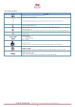
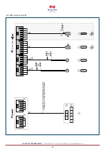
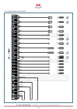
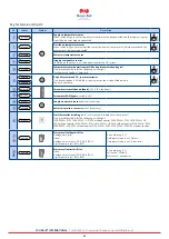
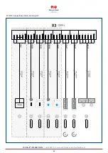
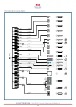
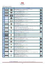
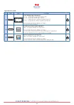
Key for terminal strips X6 and X8
No.
FeBeSy
Symbol
Description
4*
aGAxWP
Solid Air unit:
Y-G0: 0-10V; max. 10 mA
N: 0V
D1:
Enable contact (NO contact)
D2:
Heating mode (open contact)/cooling mode (closed contact)
I:
Solid Air fault
III:
Defrost mode
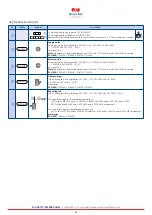
PLEASE NOTE:
Disconnect the unit from the power when making changes to the
position of the DIP switch.
Only present/available for the following unit designs:
- Systems with Solid Air.
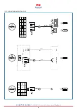
The Solid Air system includes control cables (W10 and W11) in the cable harness.
These must be wired into the control panel of the Solid Air system.
Please refer to the instructions for information about the connection.
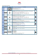
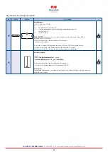
4(
Solid Air Link Pro
Note:
Under
“Contractor Menu/Misc”
change
“Interface BMS2 present” to “yes” in the BMK
Only present/available for the following unit designs:
- Systems with XL controller (KLM_XL; mat. no. 2746118).
Accessories:
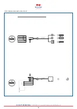
Connection information is provided in the “Solid Air Link home/Solid Air Link pro interface
module” instructions.

