37
SOLID AIR ® INTERNATIONAL
•
T +31 598 36 12 21
•
www.solid-air.com
•
9. APPENDIX
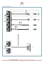
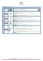
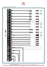
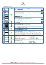
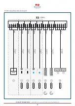
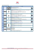
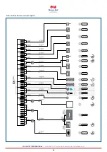
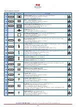
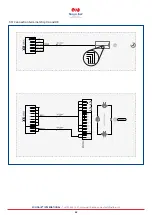
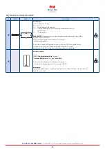
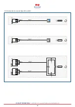
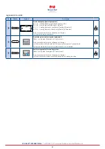
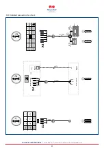
9.1 Connection diagram for CPL-1400, 2400, 3300, 4700, 6100
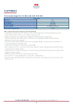
Before commissioning the control panel, note the following:
•
On appliances without control unit, the main switch must be integrated into the wiring. Rated current 25 A.
Cable harness wired to terminal strips; otherwise no other wiring.
•
Make all connections in accordance with the regulations of the local power supply utility.
•
Check all connecting screws and contact screws as well as the unassigned contacts for secure seating.
(May become loose during transport.)
•
The motor overload relays installed for the EC fans and electric heating coils are used as circuit breakers and
do not need to be set to the rated current.
•
Compare mains voltage with control panel supply voltage.
•
Max. line length for sensors, servomotors, 24V control cables 50 m. Never route together with 230/400 V cables,
or alternatively use shielded cables.
•
Listed cable cross-sections are minimum cross-sections for copper cables without taking into account the cable
length and onsite conditions.
•
Cable types must be selected according to the type of routing.
•
Frost protection is only guaranteed if mains switch Q1 is not deactivated.
•
Residual current protective device RCD. Only AC/DC-sensitive fault current safety devices, type B, with 300 mA
are permissible.
Wiring colours
Main circuit
Black
Neutral conductor
Light blue
Earth conductor
Green/yellow
Control circuit for AC
Red/red-white
Control circuit for DC
Dark blue/dark blue/white
Floating contact (external voltage)
Orange

