background image

13

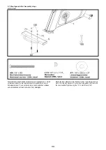
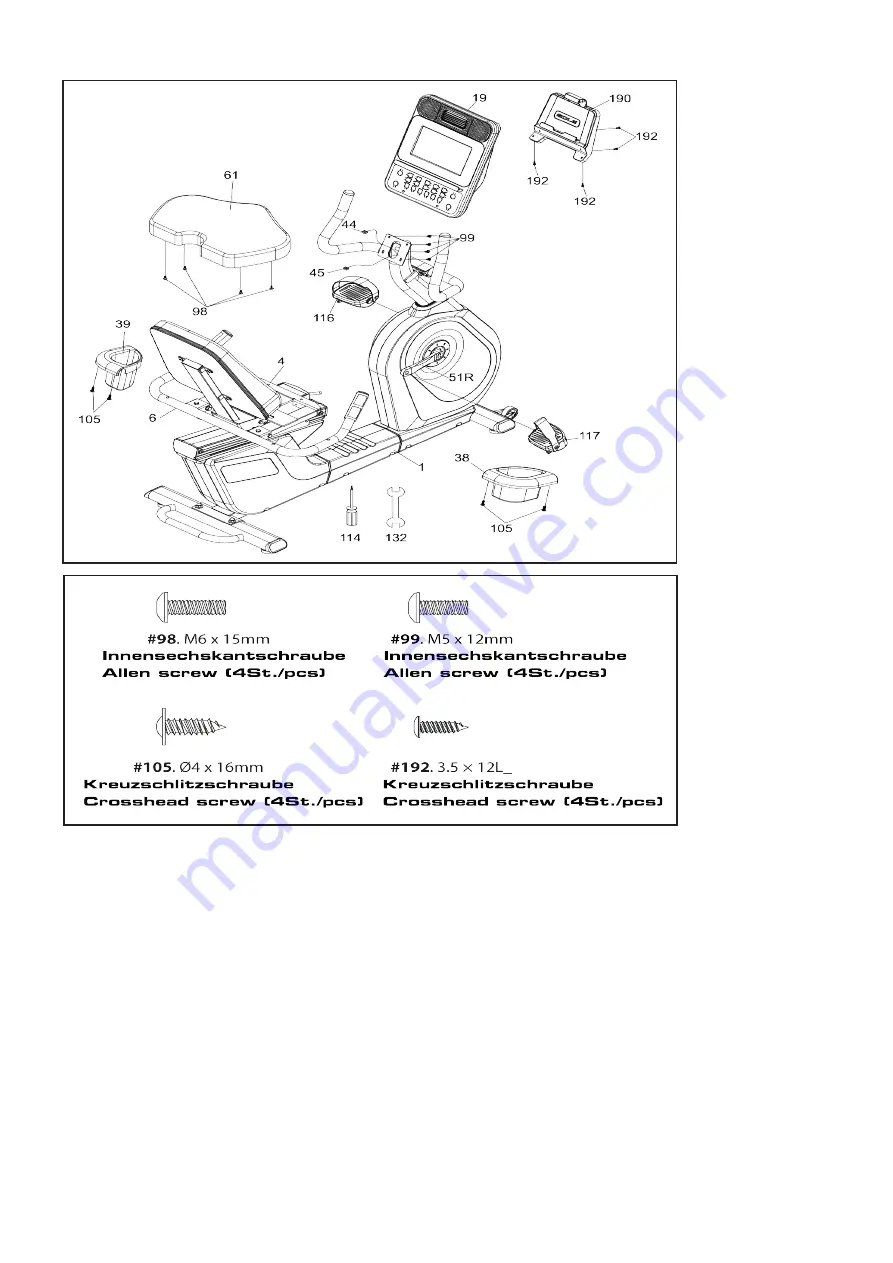
Schritt/Step 4

1. Montieren Sie das Sitzpolster (61) mit vier Kreuzschlitzschrauben (98)  
am Sitzschlitten (4).
2. Verbinden Sie das Computerkabel (44) und das Handpulskabel (45) 
mit den passenden Buchsen auf der Rückseite des Computers (19) 
und fixieren Sie den Computer (19) mit vier Kreuzschlitzschrauben 
(99) am Lenkerstützrohr (2). Achten sie darauf, dass sie die Kabel nicht 
beschädigen.
3. Die Trinkflaschenhalter (38, 39) werden mit je zwei selbstschnei-
denden Kreuzschlitzschrauben (105) am Griff (6) befestigt.
4. Montieren Sie die Pedale (116 und 117) an den Kurbeln (16), das 
linke Pedal hat ein Linksgewinde und wird deshalb nach links herum 
eingedreht. Beide Pedale sind mit L und R gekennzeichnet. Sollten die 
Pedale nach geraumer Zeit ein Klickgeräusch erzeugen, so ziehen Sie 
die Schraubverbindung nochmals fest an.
5. Befestigen Sie den Tablethalter (190) auf der Rückseite des Computers 
mit vier selbstschneidenden Kreuzschlitzschrauben (192).

1.Install the Seat (61) on the Seat Carriage (4) with the four Phillips Head 
Screws (98).
2. Plug in the Computer Cable (44) and Hand pulse Cable (45) into the 
connector in the back of the Console Assembly (19). Install the console 
onto the mounting plate with four Phillips Head Screws (99). Be careful 
not to pinch the cables between the console and the mounting plate. 
This could short the cables and damage the electronics.
3. Install the Drink Bottle Holders (39 L, 38 R) onto left and right sides of 
the Seat Handle Bar (6) with four Sheet Metal Screws (105).
4. Install the Pedals (116, 117) in the Pedal Cranks. Keep in mind that 
the Pedal (116) has a reverse thread and will be screwed into the crank 
in the opposite rotational pattern  right hand threads. There is an “L” 
stamped into the end of the threaded post of the left pedal and an “R” in 
the right. Make sure to tighten the pedals as firmly as you possibly can. 
It may be necessary to re-tighten the pedals if you notice a thumping 
sound when pedaling the bike. A clicking noise, or thumping  sound 
during pedaling is usually caused by the pedals being  loose.
5. Install the Tablet Holder (190) to back of the console with four Sheet 
Metal Screws (192)

.

Summary of Contents for 3421

Page 1: ...B94 Art Nr 3421 R92 Art Nr 3422 ...

Page 2: ...estellformular R92 1 Safety instructions 02 2 Gerneral 03 2 1 Packaging 03 2 2 Disposal 03 3 Assembly B94 03 3 1 Assembly steps 04 3 2 How to adjust the saddle postion 08 4 Assembly R92 09 4 1 Assembly steps 09 4 2 How to adjust the saddle postion 14 5 Care und Maintenance 14 6 Computer 15 6 1 Computer keys 15 6 2 Pulse measurement 16 6 3 Sole App 16 6 4 Console Sole APP Bluetooth chest strap 18 6...

Page 3: ...idung sondern geeignete Trainingskleidung wie z B einen Trainingsanzug 14 Tragen Sie Schuhe und trainieren Sie nie barfuß 15 Achten Sie darauf dass sich nicht Dritte in der Nähe des Gerätes befinden da weitere Personen durch die beweglichen Teile ver letzt werden könnten 1 Sicherheitshinweise 02 IMPORTANT The bike is produced according to EN ISO 20957 1 9 class HC and cannot be used for medical th...

Page 4: ...aining incorrect settings etc Before starting your training you should have a complete physical exa mination by your physician in order to rule out any existing health risks 2 1 Packaging Environmentally compatible and recycable materials External packaging made of cardboard Molded parts made of foam CFS free polystyrol PS Sheeting and bags made of polyethylene PE Wrapping straps made of polypropy...

Page 5: ...ie zwei Sechskantschrauben 50 und zwei Unterlegscheiben 71 von unten und durch den Hauptrahen schieben und anschließend mit zwei Hutmuttern 135 befestigen Attach the Rear Stabilizer 5 to the Main Frame 1 by sliding two Cap Nuts 135 two Flat Washers 71 onto two Carriage Bolt 50 then into the rear stabilizer Tighten using the 12 14 mm Wrench 100 ...

Page 6: ... die Schrauben an der Seite und eine gebogene Unterlegscheibe 99 für die Schraube an der Stirnseite 1 Unravel the Computer Cable 29 and pull the twist tie wire through the Console Mast Cover 38 see illustration for the correct orientation of the cover and the Console Mast 2 until the cable connector comes out the top opening of the Console Mast 2 Attach the Console Mast 2 onto the Main Frame 1 wit...

Page 7: ... die Öffnungen am Lenkerstützrohr 2 hinein und anschließend oben heraus 1 Secure the Seat Handle Bar 3 onto the Console Mast 2 with the four of Button Head Socket Bolts 74 four of Flat Washers 72 and two of Split Washers 103 by using the Combination M5 Allen Wrench 76 2 Let the two of Hand pulse W Cable Assembly 26 through the front of hole on the Console Mast 2 and outside ...

Page 8: ...onsole 34 2 Attach the Console 34 onto the Console Mast 2 with four Phillips Head Screws 58 Be careful not to pinch the cables when fastening 3 Install the Pedals 45 L 46 R onto the Cranks by using the 13 15mm Wrench 92 Remember that the left pedal has a reverse thread and will be screwed into the crank in the opposite rotation from normal threads There is an L stamped into the end of the threaded...

Page 9: ...ffnen Sie beide Muttern am Sattelgestell bis sich der Sattel leicht drehen lässt Verstellen Sie die Neigung des Sattels durch drücken oder ziehen an der Sattelspitze Ist eine komfortable Neigung erreicht drehen Sie die zuvor geöffneten Muttern der Sattelgestells mit dem passenden Werkzeug wieder zu 3 2 How to adjust the saddle postion Height of the saddle Most important is the correct height of th...

Page 10: ...e darauf dass Sie während des Zusammenbaus in jede Richtung hin genügend Bewegungsfreiraum mind 1 5m haben Bevor Sie mit dem Aufbau beginnen muss das TrainingsgerätZimmertemperatur erreicht haben In order to make assembly of the item as easy as possi ble for you we have pre assembled the most important parts Before you assemble the equipment please read these instruc tions carefully and then conti...

Page 11: ... 3 Setzen Sie die Endkappen 32 in den vorderen Standfuß ein Ggf muss ein Gummihammer verwendet werden 10 1 Attach the Rear Stabilizer 7 onto the Main Frame 1 with two Hex Head Bolts 65 and two Flat Washers 84 2 Attach the Seat Back Bracket 5 onto the Seat Carriage 4 with six Hex Head Bolts 176 and six Flat Washers 77 3 Insert an end cap 32 into each opening of the Front Stabilizer Tube You may nee...

Page 12: ...den Muttern 89 fixiert 2 Stecken Sie die Handpulskabel in die Buchsen auf der linken Seite des Gehäuses unterhalb der Sitzschiene 11 1 Install the Seat Handle Bar 6 onto the Seat Carriage 4 with two vertical Hex Head Bolts 71 two horizontal Hex Head Bolts 175 four Flat Washers 77 and four Nyloc Nuts 89 using the 12 14mm Wrench 112 and 14 15mm Wrench 132 2 Plug the two Hand pulse Cables 21 27 into ...

Page 13: ...gscheiben 76 und zwei Federringen 82 am Lenkerstützrohr 2 12 1 Install the Console Mast Cover 31 onto the Console Mast 2 Make sure the plastic cover is in the correct orientation 2 Feed the twist tie that is attached to the Computer Cable 44 and Hand pulse Cable 45 through the bottom of the Console Mast Tube 2 and out through the opening at the top 3 Install the Console Mast Tube 2 into the receiv...

Page 14: ...the Seat Carriage 4 with the four Phillips Head Screws 98 2 Plug in the Computer Cable 44 and Hand pulse Cable 45 into the connector in the back of the Console Assembly 19 Install the console onto the mounting plate with four Phillips Head Screws 99 Be careful not to pinch the cables between the console and the mounting plate This could short the cables and damage the electronics 3 Install the Dri...

Page 15: ...zentfernung sodass es für Sie am angenehms ten ist achten aber bitte darauf dass das Kniegelenk nicht durchge streckt wird 4 2 How to adjust the saddle postion Saddle position Most important is the correct distance of the seat To make sure it is correct please follow the below instruction one pedal should be in the most front position sit on the item put the foot on the pedal which is in the most ...

Page 16: ...e programming data ENTER By pressing this key a function can be confirmed 6 1 Funktionstasten FAN Schaltet den Ventilator ein und aus LEVEL Erhöhung Verringerung von Funktionswerten und Widerstand stufen Ein längeres Drücken aktiviert den Schnelldurchlauf START STOP Startet und beendet das Training Während des Trainings aktiviert das Drücken der Stop Taste die Pausenfunktion 5 Minuten ein weiteres...

Page 17: ...isplay Durch Drücken können verschiedene Werte angezeigt werden Reihenfolge Geschwindigkeit Level Widerstandsstufe Watt Zeit und Data Scan alle vier Sekunden wechselt die Anzeige PROGRAMS Jeder Programm Taste ist ein Profil zugeordnet Audio In Kopfhörerbuchse Auf der linken Seite des Computers befindet sich die Audio in Buchse in welche verschiedene Audioquellen MP3 Ipod tragbarer CD Player oder a...

Page 18: ...ol display the following circle location Hat Ihr Smarthphone Tablet das Solegerät gefunden dann drücken Sie connect Ihr Smarthphone Tablet muss min destens iOS 7 oder Android 4 4 installiert haben APP Mit den Pfeiltasten in der APP können Sie das Sole Trainingsgerät direkt steuern Das Laufband kann auch Musik über Blue Tooth abspielen Aktivieren Sie dafür BT in Ihrem Smarthphone Tablet und suchen ...

Page 19: ... mit der App verbunden ist drücken Sie dei Blue Tooth Taste Select the heart rate tracking device you use and press Connect Wählen Sie den betreffenden Brustgurt aus und drücken Connect During workout the BLE HR icon will lit up and your heart rate information will be shown on the display Während des Trainings leuchtet das BT symbol und die Herzfrequenz wird angezeigt ...

Page 20: ...m gelben Anzeigebereich 6 5 2 1 Manual Sollten Sie die Trainingsfunktion MANUAL nutzen können Sie durch Drücken der UP DOWN Tasten den Schwierigkeitsgrad Tretwiderstand in 20 Stufen einstellen Drücken Sie die ENTER Taste Im Anzeigefeld erscheint AGE Sie müssen nun mit den UP DOWN Tasten Ihr Alter eingeben und mit ENTER bestätigen Anschließend werden Sie zur Eingabe Ihres Gewichtes aufgefordert Nac...

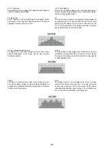
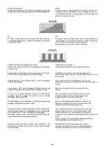
Page 21: ...ed for a variety of workouts These five programs have factory preset work level profiles for achieving different goals Hill This program follows a triangle or pyramid type of gradual progression from approximately 10 of maximum effort the level that you chose before starting this program up to a maximum effort which lasts for 10 of the total workout time then a gradual regression of resistance bac...

Page 22: ...adual progression of resistance up to 100 of maximum effort that is sustained for 25 of workout duration This will help build strength and muscular endurance in the lower body and glutes A brief cool down follows HIIT This program takes you through high levels of intensity followed by recovery periods of low intensity This program utilizes and develops your Fast Twitch muscle fibers which are used...

Page 23: ...is no reason to describe them separately You can build your own custom program by following the instructions below or you can save any other preset program you complete as a custom program Both programs allow you to further personalize it by adding your name Press the User 1 or User 2 key The Message Center will show a welcome message If you had previously saved a program the message will contain ...

Page 24: ...s set to 60 and HR2 is set to 80 of the maximum heart rate 60 is defined for fat burning and 80 for a cardiovascular exercise They both are programmed the same way To start an HRC program follow the instructions below or just select the HR1 or HR2 program then the Enter button and follow the directions in the Message Center After selecting your heart rate target the program will attempt to keep yo...

Page 25: ...Maintenance Menu Incline Calibration If there is a problem with the incline try running the calibration Press the Incline key and the Start key at the same time Hold them down for 5 seconds and then press Start to begin the calibration If the problem persists contact service department 6 5 2 5 Diagnose Software Der Computer beinhaltet eine Diagnose Software welche auch eine Umstellung metrischen a...

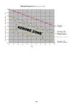
Page 26: ...en Sie später bei gleichem Puls eine höhere Leistung vollbringen was eine Verbesserung der Form bedeutet Wenn Sie mit pulsgesteuertem Training bereits Erfahrung haben können Sie Ihre gewünschte Pulszone Ihrem speziellen Trainingsplan bzw Fitnessstand anpassen Training with the Ergometer is an ideal movement training for strengthening important muscle groups and the cardio circulatory system Genera...

Page 27: ...ividuellen Leistungsfähigkeit sollte im darauffolgenden Training immer eine regene rative Trainingseinheit im unteren Pulsbereich folgen bis 75 des Maximalpulses Note Because there are persons who have high and low pulses the individual optimum pulse zones aerobic zone anaerobic zone may differ from those of the general public target pulse diagram In these cases training must be configured accordi...

Page 28: ...n wird daRüber hinaus auch Fett verbrannt Nach 30 40 Minuten wird der Fettstoffwechsel aktiviert danach ist das Körperfett der hauptsächliche Energielieferant When condition has improved higher intensity of training is required in order for the pulse rate to reach the training zone that is the organism is capable of higher performance You will recognize the result of improved condition in a higher...

Page 29: ...Zielpuls Diagramm Herzfrequenz Alter Herzfrequenz Herzschlag Min Heart Rate beats min Alter 28 Max heartrate 90 ...

Page 30: ...8 Explosionszeichnung Explosiondrawing B94 29 ...

Page 31: ...8 1 Explosionszeichnung Explosiondrawing R92 30 ...

Page 32: ...omputeroberschale Console Top Cover 1 34 2 Computerunterschale Console Bottom Cover 1 35 Gummifuß Rubber Foot 2 36 Gehäuse links Chain Cover L 1 37 Gehäuse rechts Chain Cover R 1 38 Lenkerstützrohrabdeckung Console Mast Cover 1 39 Wird nicht benötigt No needed 0 40 Abdeckung für Standfuß vorne Front Stabilizer Cover 2 41 Abdeckung für hinteren Standfuß Rear Stabilizer Cover 2 42 Griffoberschale Ha...

Page 33: ...Sattelstützrohr Locking Knob 1 107 Kunststoffbuchse für Sattelstützrohr Center spatial wrap 1 108 Wird nicht benötigt No needed 0 109 Audio Kabel optional Audio Cable optional 1 110 Wird nicht benötigt No needed 0 111 Wird nicht benötigt No needed 0 112 Wird nicht benötigt No needed 0 113 Wird nicht benötigt No needed 0 114 Spacer Spacer 1 115 Wird nicht benötigt No needed 0 116 Ablage Beverage ho...

Page 34: ... Beam Cover L 1 33R Abdeckung für Aluminiumschiene rechts Beam Cover R 1 34 Kurbelabdeckung rund Round disc cover 2 35 Gehäuse hinten links Rear Shroud L 1 36 Gehäuse hinten rechts Rear Shroud R 1 37 Wird nicht benötigt No needed 0 38 Trinkflaschehalter rechts Drink Bottle Holder R 1 39 Trinkflaschenhalter links Drink Bottle Holder L 1 40 Wird nicht benötigt No needed 0 41 Spannungskabel Transform...

Page 35: ... 110 Innensechskantschraube Flat Head Socket Bolt 3 8 x2 4 111 Innensechskantschraube Flat Head Socket Bolt M5x10 8 112 Gabelschlüssel Wrench 12 14mm 1 113 Wird nicht benötigt No needed 0 114 Kreuzschlitzschraubendreher Phillips Head Screw Driver 1 115 Wird nicht benötigt No needed 0 116 Pedal links Pedal L 1 117 Pedal rechts Pedal R 1 118 Wird nicht benötigt No needed 0 119 Mutter Nut 3 8 UNF 26x...

Page 36: ...utton Head Socket Bolt M8x15 4 180 184 Wird nicht benötigt No needed 0 185 Mutter Nut 3 8 1 186 188 Wird nicht benötigt No needed 0 189 Gummiplatte Rubber pad 1 190 1 Tablethalterung Clip Tablet holder adjustable clip 1 190 2 Tablethalterung Vorderseite Tabletholder front part 191 Hutmutter Cap nut 3 8 xUNC16x12 5 2 192 Kreuzschlitzschraube Self tapping screw ST 3 5x12 8 Bei den mit versehenen Tei...

Page 37: ...iffe von Personen vorgenommen werden die hierzu von uns nicht ermächtigt sind oder wenn unsere Geräte mit Ergänzungs oder Zubehörteilen versehen werden die nicht auf unsere Geräte abgestimmt sind ferner wenn das Gerät durch den Einfluss höherer Gewalt oder durch Umwelteinflüsse beschädigt oder zerstört ist bei Schäden die durch unsachgemäße Behandlung insbesondere Nichtbeachtung der Betriebsanleit...

Page 38: ...31 Neu Ulm Ort Datum Ersatzteilbestellung Bitte in Druckbuchstaben ausfüllen Kaufdatum Gekauft bei Firma Garantieansprüche nur in Verbindung mit einer Kopie des Kaufbeleges Bitte liefern Sie mir folgende Ersatzteile Bitte leserlich schreiben Position Bezeichnung Stückzahl Bestellgrund S E R V I C E H O T L I N E 37 Käufer Name Vorname Strasse Hausnr PLZ Wohnort Telefon Fax E Mail Adresse Lieferadr...

Page 39: ...9231 Neu Ulm Ort Datum Ersatzteilbestellung Bitte in Druckbuchstaben ausfüllen Kaufdatum Gekauft bei Firma Garantieansprüche nur in Verbindung mit einer Kopie des Kaufbeleges Bitte liefern Sie mir folgende Ersatzteile Bitte leserlich schreiben Position Bezeichnung Stückzahl Bestellgrund S E R V I C E H O T L I N E 38 Käufer Name Vorname Strasse Hausnr PLZ Wohnort Telefon Fax E Mail Adresse Liefera...

Reviews: