


5.0 Setting up the SI7500 (cont.)
502858 issue 1.1
5.0 Setting up the SI7500 (cont.)
32
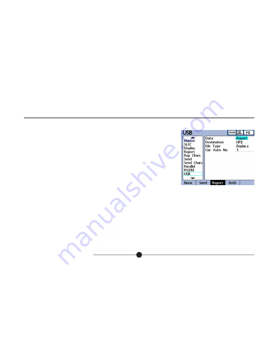
5.10.2 USB Setup
The USB screen contains fields for specifying the USB port settings for communication with a printer or
USB flash memory device.
Data:
Data can be sent to the USB port as a report formatted in the Re port Setup screen, or as record data
format ted in the Send Setup screen, or as both. The USB port can also be disabled for data transmission
by pressing the None softkey.
Destination:
Data can be sent through the USB port to be printed on a printer (HP and Epson compatible
printers are supported) or to be stored as a file on a USB flash drive. Files stored on flash drives are named
DataN.txt by the SI7500 system, where N denotes the number of the data file.
File type:
The USB port data file type can be specified to replace existing files (of the same name) on the USB flash drive, append to the existing file or create
new files that are auto-numbered sequentially in ascending order (Data1.txt, Data2.txt.....DataN.txt).
Current auto (file) number:
When the USB data file type is specified as AutoNo, the file number of the next file saved to the USB drive can be manually
specified by entering the desired number into the Cur Auto No data field. For example, entering a 2 into the Cur Auto No field will cause the next data file saved
on the USB drive to be named Data2.txt. Any file that already exists on the USB flash drive with the same name will be overwritten.


