


29
en
■
■
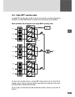
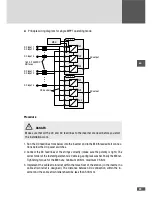
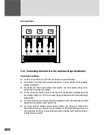
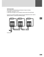
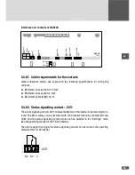
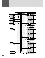
Principle wiring diagram for single MPPT operating mode:
PU1
PU2
PU3
TS-SV
PU1
PU2
PU3
TS-SV
MCU
160 A /1000VDC
NH fuses
DC input 1
DC input 2
DC input n
DC input 1
DC input 2
DC input n
DC bus bars
AC output
AC output
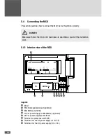
Procedure
DANGER
Make sure that all the DC and AC feed lines to the inverter are dead before you start
the installation work.
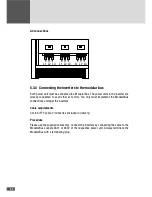
1. Run the DC feed lines from below into the inverter and to the M8 threaded bolt connec-
tions below the DC power switches.
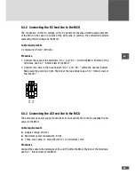
2. Connect the DC feed lines of the strings correctly; (make sure the polarity is right). The
correct order of the fastening elements is: Cable lug, spring lock washer, finally the M8 nut.
Tightening torque for the M8 nuts: minimum 20 Nm, maximum 25 Nm.
3. Implement the cable strain relief within the false floor of the station (in the inverter no
cable strain relief is designed). The distance between DC connection within the in-
verter and the cable strain relief should be less than 500 mm.
Summary of Contents for TS-SV
Page 1: ...Installation manual SolarMax TS SV 330TS SV 360TS SV...
Page 3: ......
Page 45: ...45 en...
Page 47: ...47 en...


