


33
en
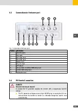
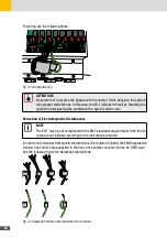
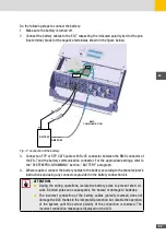
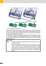
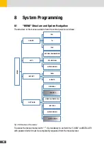
Do the following steps to connect the battery:
1. Make sure the battery is turned off.
2. Connect the battery cables to the ES-T respecting the indicated polarity (red for the pos-
itive terminal, black for the negative terminalas shown in the figure below).
RS485
RL4
NC NO CO
M
CAN BATT
CAN EX
T
LAN
_
+
_
+
BATTERY
BMS PORT
BMS
COMMUNICATION
RJ45
CAN BATT
Fig. 17: Connection of the battery
3. Connect an FTP or STP CAT5 cable with RJ45 connector between the BMS connector of
the ES-T and the battery communication connector. For the appropriate settings, refer to
the “SYSTEM PRO-GRAMMING” section, “BATTERY” paragraph.
4. Where required, connect the battery cables to the battery according to the manufacturer’s
instructions and using any connectors provided in the battery connection kit.
ATTENTION!
■
During the wiring operations, isolate the battery poles to prevent short cir-
cuits. Shorted poles can cause sparks, fire hazard or damage to batteries.
■
The incorrect connection of the battery cables (polarity reversal) does not
damage the DLX thanks to the integrated protection, but disable the operation
of the system until the correct polarity of the connection is restored. The
incorrect connection message is displayed on the LCD.
Summary of Contents for 10ES-T
Page 1: ...Instruction Manual SolarMax ES T series 5ES T 6ES T 8ES T 10ES T ...
Page 10: ...10 3 2 Function Fig 2 Function of ES T ...
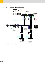
Page 22: ...22 5 2 Electrical connection diagram ES T Fig 6 Electrical connection diagram ...
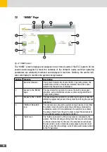
Page 74: ...74 Fig 52 Login page The HOME page will appear Fig 53 HOME page ...


