PAGE - 9
www.solarmobilityinc.com
Scenario 1:
Press the on/off button and the LED Array does not light up.
(Shark)
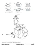
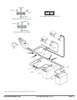
NOTE: Make sure that the batteries are fully-charged and connected properly. Refer to the battery connection diagram
on the battery box lid.
If the batteries are not fully charged and connected properly, then voltage measurements may
produce faulty readings.
Measure voltage across BATR+ and BATF- to get battery voltage. If the batteries will not
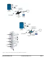
charge, go to “Scenario 2: Batteries will not charge.” Reference figures 1 and 2.
1)
Check the circuit breaker.
•
Tripped? – Reset it.
•
Not tripped? – Go to the next step.
•
Tripped but does not reset? – Remove the seat and battery box cover. Go to step 12.
2)
Measure voltage across pin 1 (B+) and pin 2 (B-) on the joystick module charger socket (JM1.)
•
0VDC? – Go to the next step.
•
18 – 25VDC (or battery voltage)? – Replace the joystick module.
CAUTION! Prevent damage to the Joystick. Be careful when touching the leads on the charger socket.
Do not touch the other pin (#3) with the multi meter leads.
3)
Disconnect the joystick harness (JH1) from the joystick module.
4)
Measure voltage across pin 1 and pin 4 on the joystick harness (JH1.)
•
0VDC? – Go to the next step.
•
18 – 25VDC (or battery voltage)? – Replace the joystick module.
5)
Remove the seat.
6)
Remove the battery box cover.
7)
Disconnect the joystick module (JM2) from the power module.
8)
Measure voltage across pin 1 and pin 4 on the power module (PM5.)
•
0VDC? – Go to the next step.
•
18 – 25VDC (or battery voltage)? – Replace joystick harness.
9)
Disconnect the power harness (PH1) from the power module.
10)
Measure voltage across pin 1 and pin 4 on the power harness (PH1.)
•
0VDC? – Go to the next step.
•
18 – 25VDC (or battery voltage)? – Replace the power module.
11)
Disconnect the power harness from the front battery (BH8) and the back battery (BH6.)
12)
Measure voltage across the front battery harness (BH6) and the back battery harness (BH8.)
•
0VDC? – Go to the next step.
•
18 – 25VDC (or battery voltage)? – Replace the power harness.
13)
Measure voltage across BATF- and BATR+.
•
0VDC? – Go to the next step.
•
18 – 25VDC? – Check for continuity across the front battery harness (BH5 and BH6) and across the
back battery harness (BH7 and BH8.) Replace as necessary.
14)
Measure Resistance across the terminals on the circuit breaker (CB1 and CB2.)
•
Less than 10 ohms? – Go to the next step.
•
Open? – Replace the circuit breaker.
Summary of Contents for liberator
Page 25: ...www solarmobilityinc com sales solarmobilityinc co PAGE 25 ASSEMBLY 100 ...
Page 26: ...www solarmobilityinc com sales solarmobilityinc co PAGE 26 ASSEMBLY 200 ...
Page 30: ...www solarmobilityinc com sales solarmobilityinc co PAGE 30 FRONT RIGHT CASTER ARM ASSEMBLY ...
Page 32: ...www solarmobilityinc com sales solarmobilityinc co PAGE 32 FRONT LEFT CASTER ARM ASSEMBLY ...
Page 34: ...www solarmobilityinc com sales solarmobilityinc co PAGE 34 REAR RIGHT CASTER ARM ASSEMBLY ...
Page 36: ...www solarmobilityinc com sales solarmobilityinc co PAGE 36 REAR LEFT CASTER ARM ASSEMBLY ...
Page 38: ...www solarmobilityinc com sales solarmobilityinc co PAGE 38 RIGHT ARMREST ASSEMBLY ...
Page 40: ...www solarmobilityinc com sales solarmobilityinc co PAGE 40 LEFTARMREST ASSEMBLY ...
Page 45: ...www solarmobilityinc com sales solarmobilityinc co PAGE 45 ...


