


PAGE - 3
www.solarmobilityinc.com
Table of Contents
About the Liberator Service Guide .............................................................................................................................. 4
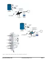
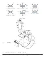
LIBERATOR COMPONENTS ..................................................................................................................................................... 4
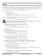
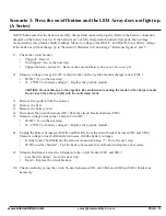
Scenario 1: Press the on/off button and the LED Array does not light up. (Shark) ............................................... 9
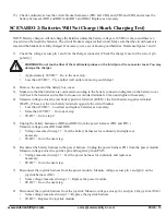
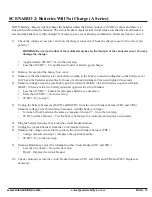
SCENARIO 2: Batteries Will Not Charge (Shark Charging Test) ........................................................................ 10
Joystick LED Array DIAGNOSTICS (Shark) ......................................................................................................... 11
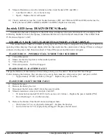
LED ARRAY “CHASE” LEFT-TO-RIGHT FOLLOWED BY A STEADY DISPLAY ......................................................... 11
FLASH CODE #1 – POSSIBLE STALL TIMEOUT OR USER ERROR .............................................................................. 11
FLASH CODE #2 – BATTERY FAULT ..................................................................................................................................... 11
FLASH CODE #3 LEFT MOTOR FAULT ................................................................................................................................ 11
FLASH CODE #4 RIGHT MOTOR FAULT ............................................................................................................................. 12
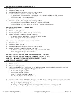
FLASH CODE #5 LEFT PARK BRAKE ................................................................................................................................... 12
FLASH CODE #6 RIGHT PARK BRAKE FAULT .................................................................................................................. 12
FLASH CODE #7 - SHARK CONTROLLER MODULE FAULT ......................................................................................... 12
FLASH CODE #8 - SHARK POWER MODULE FAULT FLASH ........................................................................................ 12
CODE #9 - SHARK COMMUNICATIONS FAULT FLASH ................................................................................................. 12
CODE #10 - UNKNOWN FAULT .............................................................................................................................................. 12
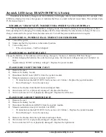
Scenario 1: Press the on/off button and the LED Array does not light up. (A Series) ......................................... 14
SCENARIO 2: Batteries Will Not Charge (A Series) .............................................................................................. 15
Joystick LED Array DIAGNOSTICS (A Series) ..................................................................................................... 16
LED ARRAY "CHASE" LEFT-TO-RIGHT FOLLOWED BY A STEADY DISPLAY ......................................................... 16
FLASH CODE #1 - POSSIBLE STALL TIMEOUT OR USER ERROR ............................................................................... 16
FLASH CODE #2 - BATTERY FAULT ...................................................................................................................................... 16
FLASH CODE #3 LEFT MOTOR FAULT ................................................................................................................................ 16
FLASH CODE #4 RIGHT MOTOR FAULT ............................................................................................................................. 16
FLASH CODE #5 LEFT PARK BRAKE ................................................................................................................................... 17
FLASH CODE #6 RIGHT PARK BRAKE FAULT .................................................................................................................. 17
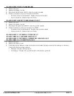
FLASH CODE #7 - INTERNAL USER FAULT ........................................................................................................................ 17
FLASH CODE #8 - CONTROLLER FAULT ........................................................................................................................... 17
FLASH CODE #9 - INTERNAL COMMUNICATIONS FAULT ............................................................................................ 17
FLASH CODE #10 - UNKNOWN FAULT ................................................................................................................................ 17
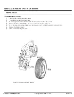
REPLACEMENT INSTRUCTIONS ........................................................................................................................ 18
DRIVE WHEEL ........................................................................................................................................................................... 18
FRONT CASTER ......................................................................................................................................................................... 19
DRIVETRAIN (MOTOR AND GEARBOX) ............................................................................................................................ 20
POWER MODULE ...................................................................................................................................................................... 22
Illustrated Parts Diagrams ........................................................................................................................................ 23
SHROUD ASSEMBLY ............................................................................................................................................................... 23
ASSEMBLY 100 ........................................................................................................................................................................... 25
ASSEMBLY 200 .......................................................................................................................................................................... 26
ASSEMBLY 300 .......................................................................................................................................................................... 28
FRONT RIGHT CASTER ARM ASSEMBLY ....................................................................................................................... 30
FRONT LEFT CASTER ARM ASSEMBLY .......................................................................................................................... 32
REAR RIGHT CASTER ARM ASSEMBLY ......................................................................................................................... 34
REAR LEFT CASTER ARM ASSEMBLY ............................................................................................................................ 36
RIGHT ARMREST ASSEMBLY ............................................................................................................................................. 38
LEFT ARMREST ASSEMBLY ................................................................................................................................................ 40
ELECTRONICS AND MISCELLANEOUS (SHARK) ............................................................................................................ 42
ELECTRONICS AND MISCELLANEOUS (A SERIES) ......................................................................................................... 43
Illustrated Parts Diagrams Solar Companion ......................................................................................................... 44
Summary of Contents for liberator
Page 25: ...www solarmobilityinc com sales solarmobilityinc co PAGE 25 ASSEMBLY 100 ...
Page 26: ...www solarmobilityinc com sales solarmobilityinc co PAGE 26 ASSEMBLY 200 ...
Page 30: ...www solarmobilityinc com sales solarmobilityinc co PAGE 30 FRONT RIGHT CASTER ARM ASSEMBLY ...
Page 32: ...www solarmobilityinc com sales solarmobilityinc co PAGE 32 FRONT LEFT CASTER ARM ASSEMBLY ...
Page 34: ...www solarmobilityinc com sales solarmobilityinc co PAGE 34 REAR RIGHT CASTER ARM ASSEMBLY ...
Page 36: ...www solarmobilityinc com sales solarmobilityinc co PAGE 36 REAR LEFT CASTER ARM ASSEMBLY ...
Page 38: ...www solarmobilityinc com sales solarmobilityinc co PAGE 38 RIGHT ARMREST ASSEMBLY ...
Page 40: ...www solarmobilityinc com sales solarmobilityinc co PAGE 40 LEFTARMREST ASSEMBLY ...
Page 45: ...www solarmobilityinc com sales solarmobilityinc co PAGE 45 ...


