1
SAB12-0429_08_Installation and Maintenance Manual SFxxx-S
2
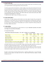
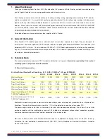
1. About this Manual
┇┇┇┇
Thank you for choosing Solar Frontier’s (SF) CIS photovoltaic (PV) modules. At Solar Frontier, we look forward to providing
you the highest standards in solar energy performance and customer service.
The following manual contains vital information on handling, installing, wiring, operating and maintaining SF PV modules,
and the associated risks. It is essential that you thoroughly understand all the instructions and warnings in this document,
together with any information provided by balance of system manufacturers, to ensure the correct and safe use of our
modules. Please share this manual with the installer/operator and keep it for future reference. BE SURE TO CONFORM
TO ALL RELEVANT LOCAL AND NATIONAL LAWS, REGULATIONS AND CODES WHEN INSTALLING, WIRING,
OPERATING AND MAINTAINING SF PV MODULES.
For additional queries, please contact your local supplier or Solar Frontier.
2. General Information
┇┇┇┇
Solar Frontier’s CIS modules generate an electrical direct current when exposed to sunlight. They are designed for
terrestrial use. The nominal power of SF PV modules indicates the power generated under Standard Test Conditions (cell
temperature: 25°C, air mass 1.5, solar irradiance 1000 W/m
2
). SF PV Module power output in actual operating conditions
may vary. The amount of electrical direct current generated by SF PV modules is proportional to irradiance intensity, while
the voltage is affected by temperature.
3. Technical Data
The technical data below represents SF PV modules distributed in all regions.
Information required by UL is marked
accordingly and is only relevant to US installers.
3.1 Electrical Characteristics
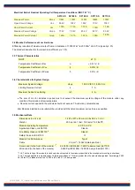
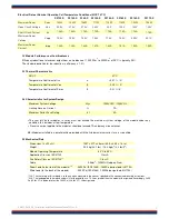
Electrical Data at Standard Test Conditions 25
°C
, AM1.5, 1000W/m
2
(UL: per ASTM E892)
SF135-S
SF140-S
SF145-S
SF150-S
SF155-S
SF160-S
SF165-S
SF170-S
Maximum Power
Pmax
135W
140W
145W
150W
155W
160W
165W
170W
Tolerance of Pmax
+10
䐗
/ -5
䐗
Open Circuit Voltage
Voc
106V
107V
107V
108V
109V
110V
110V
112V
Short Circuit Current
Isc
2.10A
2.10A
2.20A
2.20A
2.20A
2.20A
2.20A
2.20A
Maximum Power Voltage
Vmpp
80.0V
80.5V
81.0V
81.5V
82.5V
84.0V
85.5V
87.5V
Maximum Power Current
Impp
1.69A
1.74A
1.80A
1.85A
1.88A
1.91A
1.93A
1.95A
Open Circuit Voltage at -10ºC and
1,250W/m
2
irradiance
(UL)
119V
120V
120V
121V
122V
123V
123V
125V
Short Circuit Current at 75 ºC and
1,250W/m
2
irradiance
(UL)
2.64A
2.64A
2.76A
2.76A
2.76A
2.76A
2.76A
2.76A
Photovoltaic modules may produce more current and/or voltage under actual operating conditions than in Standard Test
Conditions. The electrical characteristics are within
±
10% of the indicated Isc and Voc values under STC.
The power output stated on the label is measured at the plant after module preconditioning. The values of Isc and Voc
marked on modules shall be multiplied by a factor of 1.25 to determine component voltage ratings, conductor ampacities,
overcurrent device ratings, and size of controls connected to the module output.
UL:
Refer to Section 690.8 of the National Electrical Code for an additional multiplying factor of 1.25 (80% derating).
Installation must be completed in accordance with CSA C22.1, Safety Standard for Electrical Installations, Canadian
Electrical Code, Part 1.
Summary of Contents for SF135-S
Page 10: ...6 9...
Page 11: ......
Page 14: ...8 9 B B BB 1 BB BB BB ABBB B CCC 1...
Page 18: ......
Page 49: ...SAB12 0669_02_Installation and Maintenance Manual SFxxx S 13...

