SAB12-0669_02_Installation and Maintenance Manual SFxxx-S
8
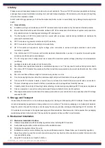
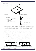
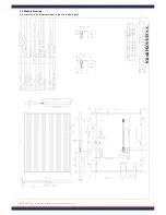
Mounting with Clamps
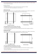
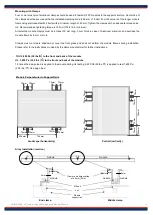
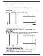
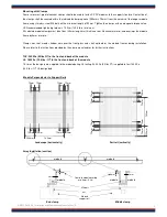
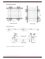
Four or more rust-proof aluminum clamps should be used to fasten SF PV modules to the support structure. Center-line of
the clamps shall be secured within the indicated clamping zone (256 mm
±
75 mm) from the corners of the longer module
frame using stainless-steel M 8 bolts with a minimum length of 20 mm. Tighten the clamps with an adequate torque value.
UL: Recommended tightening torque is 15 N-m (132.8 lb-in) minimum.
All selected module clamps must be at least 30 mm long, 3 mm thick in case of Aluminum material, and overlaps the
module frame by 8 mm or more.
Clamps must not create shadow nor cover the front glass and shall not deform the module frames during installation.
Please refer to the instructions provided by the clamp manufacturer for further instructions.
TUV: 2,400 Pa (50 lbs/ft
2
) to the front and back of the module
UL: 1,600 Pa (33.4 lbs / ft
2
) to the front and back of the module
1.5 times the design load is applied to the module during UL testing. 2,400 Pa (50 lbs /ft
2
) is applied to test 1,600 Pa
(33.4 lbs / ft
2
) UL design load.
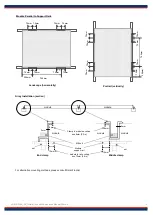
Array Installation (section)
Module Perpendicular to Support Rails
Landscape (horizontally)
Portrait (vertically)
End clamp
Middle clamp
Module
support rail
M8 bolt
module
module
nut
module
module
module
Clamp to module overlap
min 8mm (0.3in)
8mm
8mm
3mm
3mm
256mm
745mm
75mm 75mm
75mm
75mm
75mm
75mm
75mm
75mm
75
mm
75
mm
75
mm
75
mm
75
mm
75
mm
7
4
5
mm
25
6
mm
75
mm
75
mm
Summary of Contents for SF135-S
Page 10: ...6 9...
Page 11: ......
Page 14: ...8 9 B B BB 1 BB BB BB ABBB B CCC 1...
Page 18: ......
Page 49: ...SAB12 0669_02_Installation and Maintenance Manual SFxxx S 13...

