


35
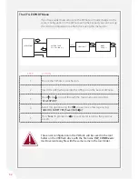
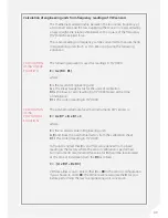
1. SWEEP
FREQUENCY:
2. EXCITATION
VOLTAGE:
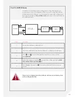
3. TEMPERATURE
UNIT:
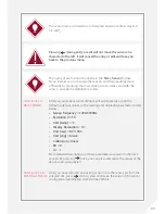
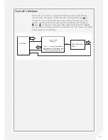
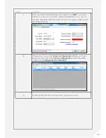
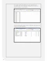
The Sensor Configuration File contains the following eight parameters
that define how each sensor is read and how the readings are displayed.
You need to set the sweep frequency to any range between 450 Hz and
6000 Hz, such as 450-1250 Hz or 1200-2800 Hz.
The default excitation voltage that VWnote uses to energise the
sensor before taking a reading is 5 VDC. This is sufficient for most site
conditions where the sensors have a short to medium cable length.
You can select the optional 15 VDC excitation if the sensor has a long
cable. The maximum cable length that 5 VDC excitation will work is
dependent on factors such as the gauge size of the wires.
However, as a rule of thumb, cable lengths greater than 200m (600ft)
are usually considered to be long.
By default, temperature readings will be displayed as °C. Optionally, you
can select °F
GUIDE TO THE CONFIGURATION FILE & DATA FILE
Content of the Sensor Configuration File
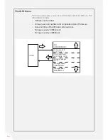
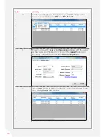
4. DISPLAY
RESOLUTION:
The display resolution for each sensor reading (in raw or engineering
units) can be set to match your needs. The default value for this
parameter is 0.1 (1 digit after the decimal point). You can select from 1 &
0.1 (equivalent to 0 & 1 digit after decimal point).
5. RAW DATA
UNIT:
This defines the raw reading (in Hz or Hz
2
/1000) that is saved and used
for conversion into reading in engineering units. The default value for
this parameter is Hz
2
/1000.
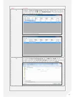
6. ENGINEERING
UNIT NAME:
This is the name of the engineering unit that you would like to use
when the reading of this sensor is displayed and saved, such as kPa, psi
and mH
2
O. It is a text string with up to 8 characters. The default value for
this parameter is “blank”.
7. CALIBRATION
FACTORS:
Calibration factors are used to convert sensor raw readings (defined
above) into values in engineering units (also defined above). The default
calibration is linear which requires a gauge factor (G) and a base reading
(R0). If you select polynomial you will need to enter A, B and R0 or C,
where the value for R0 is in raw data units, such as Hz or Hz
2
/1000.
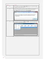
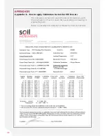
Please see
Appendix A
of this manual for a more detailed description of
the calibration factors.
Summary of Contents for RO-1 VW Note
Page 21: ...21 ...


