6
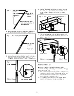
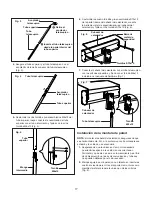
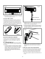
4. Secure the upper pole and the telescoping pole with the
coupler from the top of the telescoping pole (Fig. 4).
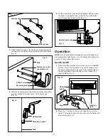
5. Unscrew 2 pre-assembled M6x12 screws from the upper
pole, then connect the upper pole assembly with the
middle pole, and tighten with the 2 M6x12 screws (Fig. 5).
6. Unscrew the 4 pre-assembled ST3x10 screws from the
back of the heater head, attach the metal safety bar on
the heater head and secure with the ST3x10 screws
(Fig. 6).
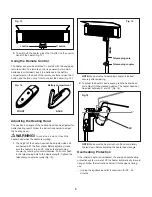
7. Connect the heater head with the telescoping pole with
the holes aligned and tighten with the M6x12 screw in the
hardware pack (Fig. 7).
Wall mount Set-up
NOTE: When mounting the heater head, make sure it's
mounted horizontally, or the tipping over protection will engage
and the unit will not start.
1.
Make sure the desired mounting location can fit the unit in
a horizontal orientation and is near an outlet but free from
electrical cables, communication lines, and pipes that
could be damaged by excessive heat.
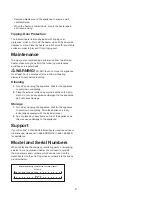
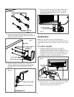
2. Pre-drill the wall and insert the 4 wall anchors. Use the
bracket as a template for hole placement (Fig. 8).
Fig. 3
Telescoping
coupler
Upper pole
Telescoping
pole
Remove the
telescoping
coupler
Insert the telescoping
pole from the bottom of
the upper pole
Telescoping pole
Fig. 4
Telescoping
coupler
Upper pole
Fig. 5
Upper pole
Middle pole
M6x12 screw
Fig. 6
Metal safety
bar
Heater head
ST3x10 screws
Fig. 7
Heater head
Telescoping pole
M6 x 12 screw


