


23
Section 5 - ADJUSTMENTS & REPAIR
FIGURE 5.12
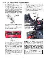
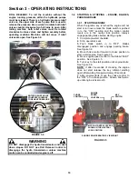
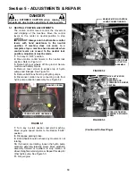
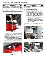
5.6a MOTION LEVER HANDLEBAR ALIGNMENT
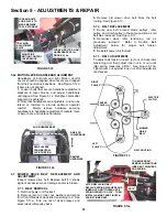
Handlebars of both left and right Motion Control
Levers should be aligned when levers are dropped
from their neutral lock positions. See Figure 5.12a.
If bars are not aligned:
1.
Loosen bolts that secure handlebar adjustment
brackets to lever blocks, and adjust handlebars
until aligned. See Figure 5.12. Retighten bolts after
alignment is achieved.
2.
Note that handlebars are adjustable, and can be
raised or lowered to provide optimum operator
comfort. Simply remove hardware securing
handlebars to handlebar adjustment brackets, raise
or lower bars, and replace hardware.
FIGURE 5.12a
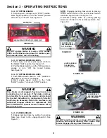
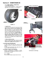
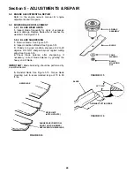
5.7 MOWER DRIVE BELT REPLACEMENT AND
ADJUSTMENT
Inspect mower drive belt. Replace belt if it shows
signs of excessive wear, damage and/or is broken.
5.7.1. BELT REMOVAL
1.
Remove power unit footrest.
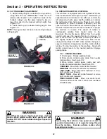
2.
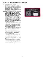
Remove jam nut, inner nut, washers and spring
from front threads of deck idler tensioning rod. See
Figure 5.13a. Slip rod out of deck bracket, and
swivel deck idler pulley back.
3.
Remove old mower drive belt. Note the belt
routing. See Figure 5.13.
5.7.2. BELT REPLACEMENT
1.
Route new belt around blade pulleys, idler
pulley, and clutch pulley in the same position as old
belt was removed. See Figure 5.13.
2.
Reconnect deck idler tensioning rod as
previously removed. Refer to Section ‘Belt
Adjustment’ below for proper belt tension
adjustment.
3.
Reinstall power unit footrest.
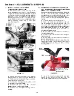
5.7.3. BELT ADJUSTMENT
To adjust belt tension, loosen jam nut on deck idler
tensioning rod, then adjust inner nut in or out until
idler spring measures 2-5/16”. See Figure 5.13a.
Tighten jam nut against inner nut after adjustment
is achieved.
FIGURE 5.13
FIGURE 5.13a
BELT ROUTING
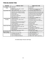
TRACKING
ADJUSTMENT
PLATE
ELECTRIC
CLUTCH
CENTER
PULLEY
RIGHT
PULLEY
LEFT
PULLEY
MOWER
DRIVE
BELT
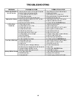
RIGHT SIDE
MOTION CONTROL
LEVER BLOCK
TO REMOVE BELT,
REMOVE JAM NUT AND
INNER NUT, WASHERS
AND SPRING
LOOSEN BOLTS. ALIGN
HANDLEBARS AS IN
FIGURE 5.12a
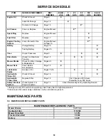
DROP LEVERS
FROM NEUTRAL
LOCK POSITION
ALIGN HANDLEBARS
REMOVE
HARDWARE
RAISE OR
LOWER BARS
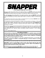
LOOSEN BOLTS.
SLIDE PLATE TO
MAKE MACHINE
TRACK STRAIGHT
AFTER REPLACING BELT,
REPLACE SPRING, WASHERS AND
INNER NUT, AND TIGHTEN UNTIL
SPRING LENGTH IS 2-5/16”. THEN
INSTALL JAM NUT AND TIGHTEN
AGAINST INNER NUT.
2-5/16”
Summary of Contents for CZT19480KWV, CZT19481KWV, HZT2
Page 33: ...33 PRIMARY MAINTENANCE...
Page 34: ...34 PRIMARY MAINTENANCE...
Page 35: ...35 PRIMARY MAINTENANCE...
Page 36: ...36 PRIMARY MAINTENANCE...
Page 38: ...38 NOTES...
Page 39: ...39 NOTES...