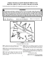
STEP 6:
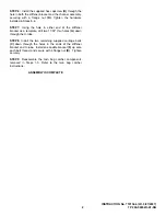
Install the supplied hex capscrew
(H)
through the
hole in both the stiffener bracket and the channel assembly,
securing with a flange nut
(D)
. Tighten the hardware
installed in Steps 5-6.
STEP 7:
Using the hole in either end of the stiffener
bracket as a template, drill two 11/32” thru holes
(G)
down
through the U-tube.
STEP 8:
Install the two remaining supplied carriage bolts
(C)
down through the holes in the ends of the stiffener
bracket and U-tube. Install one saddle bracket
(F)
up onto
each bolt thread, and secure with a flange nut
(D)
. Tighten
securely.
STEP 9:
Reassemble the twin bag catcher components
removed in Steps 1-3. Refer to the twin bag catcher
instructions.
ASSEMBLY IS COMPLETE
2
INSTRUCTION No. 7101366 (I.R. 3/27/2007)
TP 200-5265-IR-AT-SN


