background image

32

Troubleshooting, Adjustment, & Service

Tractor Troubleshooting Cont.

Tractor drive belt slips.

1.

Pulleys or belt greasy or oily. 

Clean as required.

2.

Belt stretched or worn. 

See Dealer.

3.

Idler pulley pivot bracket 

Remove idler pulley bracket, clean and lubricate.

“frozen” in declutched position. 

Brake will not hold.

1.

Internal brake worn. 

See your dealer. 

Tractor steers hard or

1.

Steering linkage is loose. 

Check and tighten any loose connections.

handles poorly.

See Steering Gear Adjustment.

2.

Improper tire inflation.

Check and correct.

3.

Front wheel spindle  

Grease spindles. See Lubricating the

bearings dry.

Tractor.

Troubleshooting the Mower

PROBLEM

CAUSE

REMEDY

Mower will not raise.

1.

Lift linkage not properly attached

Attach or repair.

or damaged.

Mower cut is uneven.

1.

Mower not leveled properly.

See Mower Adjustment.

2.  Tractor tires not inflated 

See Maintenance Section.

equally or properly.

Mower cut is rough looking.

1.

Engine speed too slow.

Set to full throttle.

2.

Ground speed too fast.

Slow down.

3.

Blades are dull. 

Sharpen or replace blades. 
See Mower Blade Service.

4.

Mower drive belt slipping

Clean or replace belt as necessary.

because it is oily or worn. 

5.

Check PTO (Electric Clutch) 

See Adjustments Section.

Adjustment.

6.

Blades not properly fastened 

See Servicing the Mower Blades.

to arbors.

Engine stalls easily with

1.

Engine speed too slow. 

Set to full throttle.

mower engaged.

2.

Ground speed too fast.

Slow down.

3.

Dirty or Clogged air filter.

See Engine Manual.

4.

Cutting height set too low.

Cut tall grass at maximum cutting
height during first pass.

5.

Discharge chute jamming 

Cut grass with discharge pointing toward

with cut grass.

previously cut area.

6.

Engine not up to operating

Run engine for several minutes to warm-up.

temperature.

7.

Starting mower in tall grass.

Start the mower in a cleared area.

Excessive mower vibration.

1.

Blade mounting screws 

Tighten to 45-55 ft - lbs. (61-75 Nm).

are loose.

2.

Mower blades, arbors, 

Check and replace as necessary.

or pulleys are bent.

3.

Mower blades are out 

Remove, sharpen, and balance blades.

of balance.

See Servicing the Mower Blades.

4.

Belt installed incorrectly.

Reinstall Correctly.

Excessive belt wear or breakage.

1.

Bent or rough pulleys. 

Repair or replace.

2.

Using incorrect belt.

Replace with correct belt.

Mower drive belt slips 

1.

Idler pulley spring broken or not 

Repair or replace as needed.

or fails to drive.

properly attached.

2.

Belt stops out of adjustment. 

Check belt stops.

3.  Mower drive belt broken. 

Replace drive belt.

4.

PTO clutch out of adjustment.

Adjust PTO clutch.

Summary of Contents for 2690782

Page 1: ... HP Simplicity Regent XL RD 19 5 HP OHV 2690784 19 5 HP Snapper ELT19540RD 22 HP Hydro Tractors Mfg No Title Description 2690783 22 HP Simplicity Regent XL RD 22 HP V Twin 2690785 22 HP Snapper ELT2240RD Regent XL RD Series 1736042 Revision 00 Rev Date 1 2008 TP 100 4841 00 RG SN ...

Page 2: ......

Page 3: ...ating the Tractor 13 Safety Interlock System 13 General Operating Safety 13 Adding Fuel 13 Starting the Engine 13 Stopping the Tractor Engine 14 Driving the Tractor 14 Mowing 14 Mowing in Reverse 14 Attachment Operation in Reverse 14 Pushing the Tractor by Hand 14 Mower Deck Removal Installation 15 Catcher Removal Installation 16 Mower Cutting Height 17 Attaching a Trailer 17 Storage 17 Regular Ma...

Page 4: ...tion of the product s features and controls and maintenance information is included to help you get the most out of your equipment investment Be sure to completely read the Safety Rules and Information found on the following pages Also completely read the Operation section Children Tragic accidents can occur with children Do not allow them anywhere near the area of operation Children are often att...

Page 5: ...this equipment safely it is equipped with an operator present safety system Do NOT attempt to alter or bypass the system See your dealer immediately if the system does not pass all the safety interlock system tests found in this manual Thrown Objects This unit has spinning mower blades These blades can pick up and throw debris that could seriously injure a bystander Be sure to clean up the area to...

Page 6: ... and practical instruction 22 Always wear substantial footwear and trousers Never operate when barefoot or wearing sandals 23 Before using always visually check that the blades and blade hardware are present intact and secure Replace worn or damaged parts 24 Disengage attachments before refueling removing an attachment making adjustments unless the adjustment can be made from the operator s positi...

Page 7: ... loose traction 5 Always keep unit in gear especially when traveling down slopes Do not shift to neutral and coast downhill 6 Avoid starting stopping or turning on a slope If tires lose traction disengage the blade s and proceed slowly straight down the slope 7 Keep all movement on slopes slow and gradual Do not make sudden changes in speed or direction which could cause the machine to rollover 8 ...

Page 8: ...e may ignite Do not spread fuel line clamps further than necessary Ensure clamps grip hoses firmly over the filter after installation 12 Do not use gasoline containing METHANOL gasohol containing more than 10 ETHANOL gasoline additives or white gas because engine fuel system damage could result 13 If the fuel tank must be drained it should be drained outdoors 14 Replace faulty silencers mufflers 1...

Page 9: ... Number Dealer Name Date Purchased Engine Make Engine Type Spec Engine Model Engine Code Serial Number Mower Deck MFG Number Mower Deck SERIAL Number CE Identification Tag Markings A Manufacturer s Identification Number B Manufacturer s Serial Number C Power Rating in Kilowatts D Maximum Engine Speed in Rotations per Minute E Manufacturer s Address F Year of Manufacture G CE Compliance Logo H Mass...

Page 10: ...fety Decals This unit has been designed and manufactured to provide you with the safety and reliability you would expect from an industry leader in outdoor power equipment manufacturing Although reading this manual and the safety instructions it contains will provide you with the necessary basic knowledge to operate this equipment safely and effectively we have placed several safety labels on the ...

Page 11: ...sion Release Part No 1735265 173xxxx Operating Instructions CE Models Part No 1734027 Attachment Lift Part No 1730264 Fuel Level Part No S532 0 8732 762 3 R 4 3 2 R 4 3 2 Ignition Switch Positions Part No 1722806 Decal Locations ...

Page 12: ...e the lever forward to close the choke Headlights The light switch turns the tractor headlights on and off Hour Meter The hour meter measures the number of hours the key has been in the RUN position Control Functions The information below briefly describes the function of individual controls Starting stopping driving and mowing require the combined use of several controls applied in specific seque...

Page 13: ...ound speed control pedal Depressing either pedal will increase ground speed Note that the further down the pedal is depressed the faster the tractor will travel Cruise Control The cruise control is used to lock the ground speed control in forward The cruise control has five lock positions 11 Features Controls Mower Lift Lever The mower lift lever controls the mower cutting height Pull lever to low...

Page 14: ... the parking brake depress the brake pedal B Cruise Control Operation TO ENGAGE 1 Pull up on the cruise control knob D Figure 2 2 Depress the forward ground speed pedal A 3 Lift up the cruise control knob D when desired speed is reached The Cruise will lock in one of its five locking positions TO DISENGAGE 1 Depress the brake pedal B OR 2 Depress the forward ground speed pedal A Hour Meter The hou...

Page 15: ... use gasoline containing METHANOL gasohol containing more than 10 ETHANOL gasoline additives or white gas because engine fuel system damage could result Safety Interlock System Tests This unit is equipped with safety interlock switches and other safety devices These safety systems are present for your safety do not attempt to bypass safety switches and never tamper with safety devices Check their ...

Page 16: ...sed while the PTO is on and the RMO has not been activated The operator should always turn the PTO off prior to driving across on roads paths or any area that maybe used by other vehicles Sudden loss of drive could create a hazard WARNING Mowing in reverse can be hazardous to bystanders Tragic accidents can occur if the operator is not alert to the presence of children Never activate RMO if childr...

Page 17: ...move the key and apply parking brake 2 Place mower in the lowest cutting position using the mower lift lever A Figure 3 3 Place the mower lift lever A in the lowered position 4 Disconnect the hair pins A Figure 4 from the trunions B on both sides of the mower deck Remove trunions from mower deck lift arms C Re install the hair pins to prevent loss 5 Remove upper spring D and the two lower springs ...

Page 18: ...unions B to mower deck lift arms C Secure with hair pins A 8 Move idler arm A Figure 5 to increase belt tension 9 Align and connect the discharge tube and mower discharge opening 10 Install the grass catcher see Catcher Removal Installation 11 Adjust mower deck if necessary see Cutting Height Adjustment section Catcher Removal Installation WARNING Do not operate the unit without the hopper or defl...

Page 19: ...n source such as a furnace water heater etc and cause an explosion Fuel vapor is also toxic to humans and animals Storage Before you store your unit for the off season read the Maintenance and Storage instructions in the Safety Rules section then perform the following steps Disengage the PTO set the parking brake and remove the key Perform engine maintenance and storage measures listed in the engi...

Page 20: ... 22 x 10 0 8 10 0 68 20 x 8 0 8 10 0 68 15 x 6 0 6 12 14 0 82 0 96 SAFETY ITEMS Before Each Use Every 5 Hours Every 25 Hours Every 100 Hours Every 250 Hours Spring Fall Check Safety Interlock System Check Tractor Brakes Check Mower Blade Stopping Time TRACTOR MAINTENANCE ITEMS Before Each Use Every 5 Hours Every 25 Hours Every 100 Hours Every 250 Hours Spring Fall Check Timing Belt Tension Check M...

Page 21: ...section of this manual Engine Maintenance Refer to the engine owner s manual for all engine maintenance procedures and recommendations Battery Maintenance Cleaning the Battery and Cables Service Interval Every 100 Hours 1 Disconnect the cables from the battery negative cables first A Figure 12 then the cover and positive cables B 2 Loosen the wingnut and washer D 3 Pivot the hold down rod C up and...

Page 22: ...A Hood Removal and Installation HOOD REMOVAL 1 Open the hood 2 Remove the socket and bulbs A Figure 14 by twisting the socket counterclockwise and pulling it out of the bezel B Repeat on other side 3 Rock the hood back slightly and lift hood B Figure 16 off pivot posts C Set hood on a clean and flat surface HOOD INSTALLATION 1 Set hinge posts A Figure 15 onto pivot posts C 2 Roll the hood forward ...

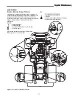
Page 23: ... should be oiled where contact is made with other parts Keep oil and grease off belts and pulleys Wipe surfaces clean before and after lubrication Grease steering linkage mower linkage rear axle shafts remove wheel hubs front axle pivot Use grease fittings when present Automotive lithium grease is recommended Oil foot pedal rods brackets seat adjustment assembly draglink mower deck height adjustme...

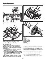
Page 24: ...r than required for wheel removal Figure 21 Rear Axle Hardware A Key B Spacer C Wheel Hub D Special Washer E Small Washer F E Clip G Axle Cap H Large Washer G B D A E F C Figure 18 Arbor Lubrication Points Figure 19 Lubricate Deck Linkage Typical H H Figure 20 Mower Lubrication Points 3 Support the rear of the unit on jackstands positioned under the rear frame NOTE Your axle assembly may differ sl...

Page 25: ... Remove mower deck see Mower Deck Removal 2 See Figure 22 To remove blade for sharpening use a block of wood to prevent blade rotation while loosening the capscrew 3 Remove the capscrew A Figure 24 spring washer B spline washer E alignment pin C and blade D Do not remove the blade adapter F 4 Use a file to sharpen blade to a fine edge If blade is damaged it must be replaced 5 Balance the blade as ...

Page 26: ...endicular to each other as shown in Figure 25 If not proceed to step 3 3 See Figure 22 Use a block of wood to prevent blade rotation while loosening the capscrew 4 Remove the capscrew A Figure 24 spring washer B and spline washer E 5 Remove the alignment pin C Rotate the blade D manually until the blades are perpendicular to each other as shown in Figure 25 It may be necessary to remove and rotate...

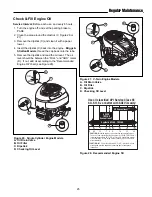
Page 27: ... Oil Filter C Dipstick D Checking Oil Level A C D B Figure 26 Single Cylinder Engine Models A Oil Drain Valve B Oil Filter C Dipstick D Checking Oil Level A C D B Figure 28 Recommended Engine Oil Use oil classified API Service Class SF SG SH SJ or better with SAE Viscosity 100 80 60 40 20 32 0 20 38 27 16 4 7 0 18 30 F C 30 Conventional Synthetic 5W 30 10W 30 5W 30 10W 30 Conventional CAUTION Air ...

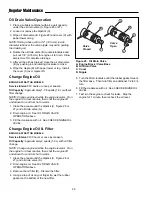
Page 28: ...he engine is warm Run the engine for a few minutes then shut the engine off and allow it to cool from hot to warm 1 Clean the area around the dipstick C Figure 26 or 27 and oil drain valve A 2 Drain engine oil See OIL DRAIN VALVE OPERATION above 3 Fill the crankcase with oil See CHECK ENGINE OIL LEVEL Change Engine Oil Filter BRIGGS STRATTON MODELS Service Interval 100 hours or once per season Oil...

Page 29: ...he air filter C as shown 4 Install the cover B making sure the tabs are inserted into their slots Secure by turning screws clockwise until snug Pre Cleaner Service NOTE Replace a worn or damaged pre cleaner 1 Wash the pre cleaner in liquid detergent and water see Figure 31 2 Squeeze the pre cleaner dry and saturate with engine oil Remove all excess oil by squeezing the pre cleaner in an absorbent ...

Page 30: ...g 5 Install the pre cleaner D with the mesh side up Install the air filter C as shown 6 Install the cover B making sure the tabs are inserted into their slots Secure with the latch A Pre Cleaner Service NOTE Replace a worn or damaged pre cleaner 1 Wash the pre cleaner in liquid detergent and water see Figure 31 2 Squeeze the pre cleaner dry Do not oil pre cleaner Air Filter Service NOTE Replace a ...

Page 31: ...stor Spark Plug Champion RC12YC 1 Stop the engine and allow it to cool 2 Clean the area around the spark plug see Figure 34 or 35 3 Remove the spark plug 4 Check the spark plug gap It should be 030 5 Reinstall the plug into the cylinder head Tighten the plug to 180 in lbs 20 Nm Figure 35 Spark Plug Gapping Regular Maintenance ...

Page 32: ...30 Regular Maintenance ...

Page 33: ... See your dealer 12 Spark plug s faulty fouled Clean and gap or replace or incorrectly gapped See engine manual 13 Water in fuel Drain fuel refill with fresh fuel Replace fuel filter 14 Gas is old or stale Drain fuel refill with fresh fuel Replace fuel filter Engine starts hard or runs poorly 1 Fuel mixture too rich Clean air filter Check choke adjustment 2 Spark plug s faulty fouled or Clean and ...

Page 34: ... 5 Check PTO Electric Clutch See Adjustments Section Adjustment 6 Blades not properly fastened See Servicing the Mower Blades to arbors Engine stalls easily with 1 Engine speed too slow Set to full throttle mower engaged 2 Ground speed too fast Slow down 3 Dirty or Clogged air filter See Engine Manual 4 Cutting height set too low Cut tall grass at maximum cutting height during first pass 5 Dischar...

Page 35: ...m or other electrical component If there is any doubt about the cause of the problem see your dealer If you need to replace the battery follow the steps under Cleaning the Battery Cables in the Regular Maintenance Section To charge the battery follow the instructions provided by the battery charger manufacturer as well as all warnings included in the Safety Rules section of this book Charge the ba...

Page 36: ...e windows for an equal amount of tension when the gauge is inserted and removed and make any necessary adjustments by tightening or loosening the adjustment nuts NOTE The actual air gap between the rotor and armature may vary even after performing the adjustment procedure This is due to dimensional variations on component parts and is an acceptable condition 6 Check the mower blade stopping time T...

Page 37: ... Replacement A PTO Pulley B Idler Assembly C Mower Arbor Drive Belt D Idler Pulley E Mower Pulley 4 F Mower Belt 6 Remove the mover belt cover to access the mower pulleys E and mower belt F 7 Remove the old belt and replace with a new belt Route the belt as shown in Figure 41 8 Check that the blades are positioned perpendicular to each other see Figure 42 If not perform the Check Mower Blade Timin...

Page 38: ...cover for the PTO pulley A Figure 43 4 Unhitch the idler spring B from the hole at the frame bracket 5 Remove the PTO belt C 6 Install a new belt on the PTO pulley A and idler pulley D as shown 7 Hitch the idler spring back on the frame bracket NOTE The PTO belt of the mower is tensioned by means of a pulley with a spring If the tension releases increase it by placing the eye of the spring into th...

Page 39: ...gas engine models is labeled in accordance with SAE Society of Automotive Engineers code J1940 Small Engine Power Torque Rating Procedure and rating performance has been obtained and corrected in accordance with SAE J1995 Revision 2002 05 Torque values are derived at 3060 RPM horsepower values are derived at 3600 RPM Actual gross engine power will be lower and is affected by among other things amb...

Page 40: ...Up Paint Grease Gun Kit 8 oz Grease Tube Tire Sealant Degrimer Degreaser Gas Stabilizer Maintenance Items Many convenient and helpful service and maintenance items are available from you authorized dealer Some of these items include Model Mfg No Your Name Address City State Zip Visa Mastercard No Card Expiration Date ...

Page 41: ......

Page 42: ...53074 0997 www MasseyLawn com MANUFACTURING INC 500 N Spring Street PO Box 997 Port Washington WI 53074 0997 www SimplicityMfg com Briggs Stratton Yard Power Products Group Copyright 2008 Briggs Stratton Corporation Milwaukee WI USA All Rights Reserved ...

Reviews: