CEBORA S.p.A.
30
5.5
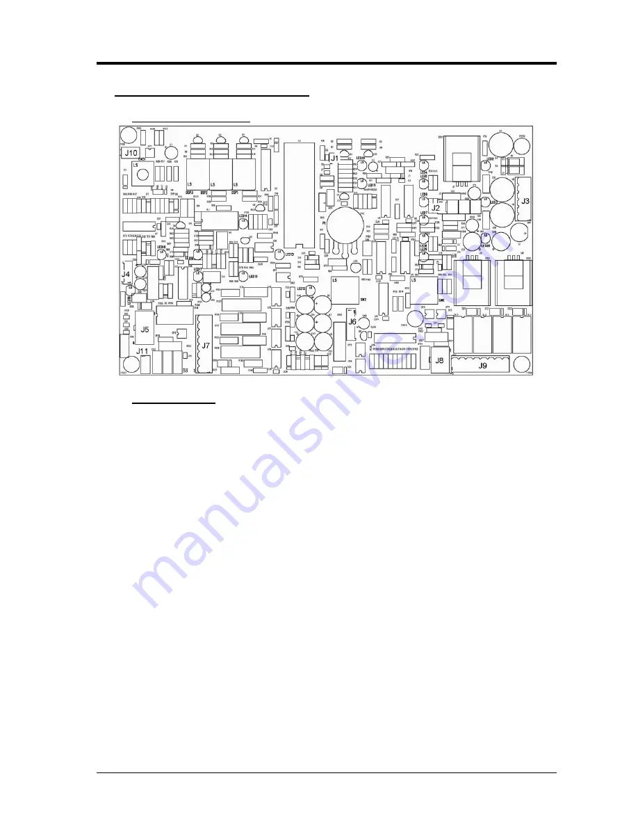
- Control board (40), code 5.602.293/A.
5.5.1
- Topographical drawing.
5.5.2
- Connector table.
Conn. Terminals Function
J1
1 - 2
NU.
J2
1 - 2
16 Vac input, synchronization signal for control board (40).
J3
1 - 4(0v) - 2 dual 16 Vac input to control board (40) power supply (+/-15 Vdc).
J3
5 - 4(0v) - 6 dual 8 Vac input to control board (40) power supply (+5 Vdc).
J4
1
-15 Vdc output to current transducer (5) power supply.
J4
2
0 Vdc output to current transducer (5) power supply.
J4
3
+15 Vdc output to current transducer (5) power supply.
J4
4
power source output current signal input.
J5
1 - 2
26 Vac input to start command circuit power supply on control board (40).
J5
3 - 4
“start” signal input.
J5
5
NU.
J5
6(+) - 8(-)
+5 Vdc output to external current potentiometer power supply.
J5
7
reference current signal input from external potentiometer cursor.
J6
1 - 2
6.5 Vac input to pulse generator for SCR1 power supply, on control board (40).
J6
4 - 5(0v) - 6 dual 6.5 Vac input to pulse generators for SCR2 and SCR3 power supply, on control board
(40).
J7
1 - 3(gnd)
“oxide destruction high voltage pulse” signal input.
J7
2
NU.
J7
4(G) - 3(K)
gate command output for SCR2 (47).
J7
5
NU.
J7
6(G) - 3(K)
gate command output for SCR3 (SC1 and SC2 on shut-off board (48)).
J7
8(G) - 7(K)
gate command output for SCR1 (47).
J8
1 - 2
input 26 Vac to protection circuit power supply.
J8
3 - 4
input signals from thermostats and cooling unit.
J8
5 - 6
AC operation enable input.
J9
1 - 2
solenoid valve (43) command output.
J9
3 - 4
2nd shut-off circuit enable relay command input, on shut-off board (48).
J9
5 - 6
AC power supply output to HF board (42) power circuit power supply.
J9
7 - 8
27 Vac command output for HF enable relay.
J10
1 - 2
converter output voltage signal input.
J11
-
earth
connection.
3.302.221
15/01/07
Summary of Contents for TIG 250 AC-DC
Page 1: ...CEBORA S p A 1 TIG 250 AC DC POWER SOURCE art 236 76 SERVICE MANUAL 3 302 221 15 01 07 ...
Page 35: ......
Page 37: ......


