Scanner
Viewing and Saving Data (PIDs)
34
5.4.9 Using Triggers
Trigger Description and Features
Setting PID triggers allows you to configure the diagnostic tool to
automatically save PID data to a file, when a PID value meets an upper/
lower limit (trigger point).
When a PID value meets the trigger point it activates the trigger which
captures a short recording of all available PID data and saves it as a data file.
You can review the saved data file to closely evaluate not only the PID that triggered
the event, but all the PIDs being monitored to collectively see what was happening
at the time of the event.
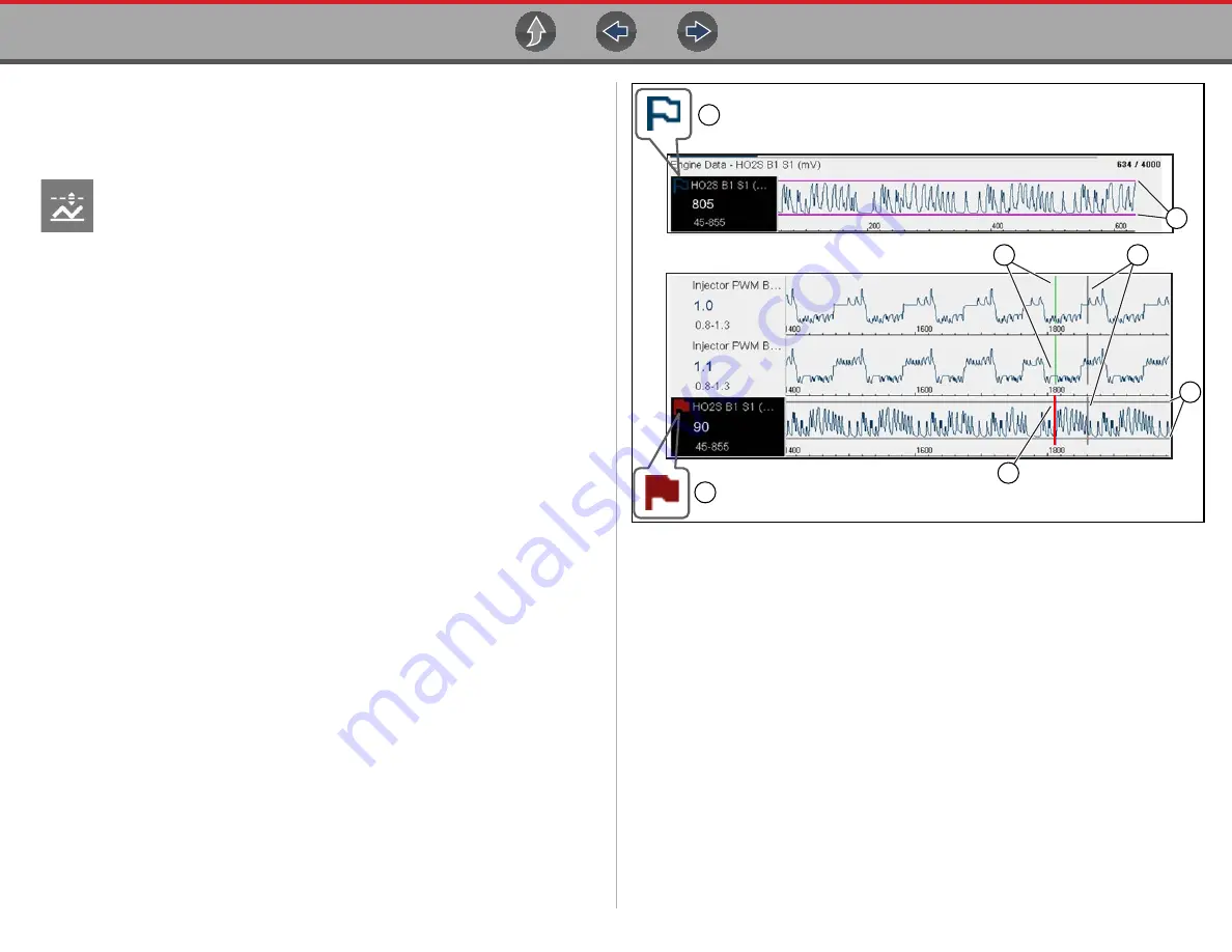
Examples of the following trigger states (Armed / Not Activated - upper image) and
(Activated - lower image) are shown in (
Figure 5-36
1— Armed PID Trigger Indicator
- A blue outlined flag indicates the PID trigger
is armed.
2— Upper and Lower Limit Lines (Armed)
- Colored limit lines indicate the
trigger is armed but not activated.
3— Trigger Activation Point Reference Cursor
- Green cursors lines are
displayed on all the other PID graphs to indicate their relationship to where
the trigger occurred.
4— Pause Cursor
- A vertical gray cursor line is displayed (all PIDs) as a marker
in the where the data was paused and the file was saved.
5— Activated PID Trigger Indicator
- A red flag indicates the PID trigger has
activated.
6— Trigger Activation Point Cursor
- A red cursor line is displayed in the PID
data where the trigger was activated.
7— Upper and Lower Limit Lines (Not Armed and Activated)
- Gray limit lines
are displayed when the trigger is armed but not activated and after the trigger
has been activated.
6
1
5
2
7
4
3


