background image

SMOOTH CE7.4 ELLIPTICAL TRAINER 


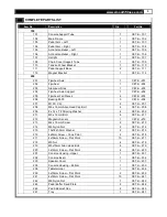
COMPLETE PARTS LIST 


Item No. 

Description 

Qty. 

Part No. 


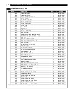
248 

Tray Cap – Left 

CE7.4i – 248 

249 

Tray Cap – Right 

CE7.4i – 249 

251 

Crank Disk Support Cover 

CE7.4i – 251 

252 

Crank Disk Axle 

CE7.4i – 252 

253 

25x35xT2.0 Washer 

CE7.4i – 253 

254 

Crank Disk Oval Cap 

CE7.4i – 254 

255 

Crank Disk Cover 

CE7.4i – 255 

256 

Crank Disk 

CE7.4i – 256 

257 

Left Crank 

CE7.4i – 257 

258 

Right Crank 

CE7.4i – 258 

259 

Crank Axle Bushing 

CE7.4i – 259 

260 

M8x45mm Bolt 

CE7.4i – 260 

261 

Pedal Arm Support Axle 19x80.4mm 

CE7.4i – 261 

262 

Pedal Arm Support Axle 19x104.4mm 

CE7.4i – 262 

264 

3/4” Nut 

CE7.4i – 264 

266 

M8x15mm Allen Head Bolt 

CE7.4i – 266 

267 

M6x12mm Allen Head Cap Bolt 

CE7.4i – 267 

268 

M8x20mm Bolt 

CE7.4i – 268 

269 

8x14xT2.0 Spring Washer 

CE7.4i – 269 

270 

M6x12mm Screw 

CE7.4i – 270 

271 

10x16x1.5mm Washer 

CE7.4i – 271 

272 

6x10x1mm Spring Washer 

CE7.4i – 272 

273 

Fan Bracket – Top  

CE7.4i – 273 

274 

Fan Bracket – Bottom 

CE7.4i – 274 

275 

Adjustable Vane 

CE7.4i – 275 

276 

Dock Bracket Cover 

CE7.4i – 276 

277 

Amplifier Board 

CE7.4i – 277 

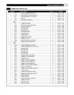
279 

Pad Holder Skidproof Foam 

CE7.4i – 279 

285 

Bearing Sleeve 

CE7.4i – 285 

286 

M8x30mm Allen Head CAP Bolt 

CE7.4i – 286 

287 

M10x25mm Allen Head CAP Bolt 

CE7.4i – 287 

288 

Bushing 25X32X6mm 

CE7.4i – 288 

289 

19x25x6mm Washer 

CE7.4i – 289 

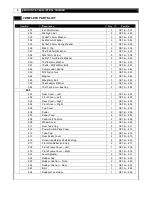
300


301 

Action Handlebar Foam Grip 

CE7.4i – 301 

302 

Hand Pulse Sensor 

CE7.4i – 302 

303 

Action Handlebar End Cap 

CE7.4i – 303 

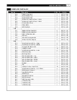
304 

Bearing 6004 

CE7.4i – 304 

305 

Action Handlebar Cover 

CE7.4i – 305 

306 

Action Handlebar Front Cover 

CE7.4i – 306 

307 

4x12mm Plastic Screw 

CE7.4i – 307 

308 

4x12mm Screw – Cone Point 

CE7.4i – 308 


Summary of Contents for CE 7.4

Page 1: ...USER S MANUAL SMOOTH CE7 4 ELLIPTICAL TRAINER USER WEIGHT LIMITATION 350lbs 160kgs SERIAL NUMBER found on frame...

Page 2: ...have gathered all the necessary tools you may require to assemble the unit properly Having all of the necessary equipment at hand will save time and make the assembly quick and hassle free Clear your...

Page 3: ...ble this product No Description Qty 842 651 Pedal Arm Front Pivot Cover 37mm 2 654 Pedal Arm Front Pivot Cover 32mm 2 656 Console Back Cover 1 657 Water Bottle 1 659 Chest Belt 1 842 MP3 Connection Wi...

Page 4: ...use the scale below to measure them and compare them to the sizes listed No Description Qty 217 4x10mm Screw Flat Point 3 701 M6x35mm Allen Head Bolt 2 702 M8x40mm Allen Head Bolt 2 703 20x91 M14x25mm...

Page 5: ...06 207 M10 C Clip 2 CE7 4i 207 208 M8 x 15mm Allen Head Cap Bolt 4 CE7 4i 208 209 8 x 14 x T2 0 Spring Washer 4 CE7 4i 209 211 M5 x 12mm Bolt 8 CE7 4i 211 212 Magnetic Sensor 1 CE7 4i 212 213 M4 x 15m...

Page 6: ...8x20mm Bolt 2 CE7 4i 268 269 8x14xT2 0 Spring Washer 3 CE7 4i 269 270 M6x12mm Screw 1 CE7 4i 270 271 10x16x1 5mm Washer 1 CE7 4i 271 272 6x10x1mm Spring Washer 4 CE7 4i 272 273 Fan Bracket Top 1 CE7 4...

Page 7: ...502 Fixed Handlebar Foam Grip 2 CE7 4i 502 503 Fixed Handlebar Side Foam Grip 2 CE7 4i 503 504 Bearing 2203 2 CE7 4i 504 505 Bearing 6005 2 CE7 4i 505 506 Bearing 6300 4 CE7 4i 506 507 Bearing 6804 4...

Page 8: ...3 554 10x17x23 5 mm Bushing 2 CE7 4i 554 600 601 Rear Cover Left 1 CE7 4i 601 602 Front Cover Left 1 CE7 4i 602 603 Rear Cover Right 1 CE7 4i 603 604 Front Cover Right 1 CE7 4i 604 605 Top Cover 1 CE7...

Page 9: ...2 CE7 4i 813 814 Hand Pulse Sensor Wire Middle 2 CE7 4i 814 815 Computer PC Board IHP 1 CE7 4i 815 818 2 6x6mm Screw 12 CE7 4i 818 822 Hand Pulse Sensor Wire Lower 2 CE7 4i 822 823 Motor Assembly 1 CE...

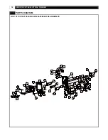
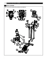
Page 10: ...10 SMOOTH CE7 4 ELLIPTICAL TRAINER PARTS DIAGRAM MOST OF THE PARTS SHOWN HERE HAVE BEEN PRE ASSEMBLED...

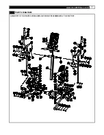
Page 11: ...www smoothfitness com 11 PARTS DIAGRAM A MAJORITY OF THE PARTS SHOWN HERE HAVE BEEN PREASSEMBLED AT THE FACTORY...

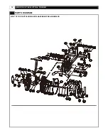
Page 12: ...12 SMOOTH CE7 4 ELLIPTICAL TRAINER PARTS DIAGRAM MOST OF THE PARTS SHOWN HERE HAVE BEEN PRE ASSEMBLED...

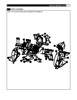
Page 13: ...www smoothfitness com 13 PARTS DIAGRAM MOST OF THE PARTS SHOWN HERE HAVE BEEN PRE ASSEMBLED...

Page 14: ...TICAL TRAINER PARTS DIAGRAM MOST OF THE PARTS SHOWN HERE HAVE BEEN PRE ASSEMBLED 829 839 837 838 836 833 845 277 841 843 844 840 834 827 832 451 825 826 827 832 832 831 830 814 814 822 822 823 813 828...

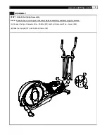
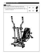
Page 15: ...Upright Assembly NOTE Please ensure not to pinch the wires while assembling and fastening the screws A Connect the 8pin Computer Wire Middle 831 and 8pin Computer Wire Lower 832 B Slide the Upright 1...

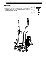
Page 16: ...2 Assemble the Pedal Arm Right A Slide the 20x91 M14x25mm Bolt 703 with 20 7x29 1x0 3mm Wave Washer 706 through the Pedal Arm Right 104 and Action Handlebar Right 106 then secure using one M14 Nut 70...

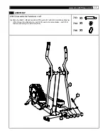
Page 17: ...MBLY STEP 3 Assemble the Pedal Arm Left A Slide the 20x91 M14x25mm Bolt 703 with 20 7x29 1x0 3mm Wave Washer 706 through the Pedal Arm Left 103 and Action Handlebar Left 105 then secure using one M14...

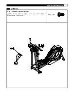
Page 18: ...ssemble the both side of Pedal Arm Front Pivot Cover A Attach the Pedal Arm Pivot Cover 37mm 651 and Pedal Arm Pivot Cover 32mm 654 into the bushing of the Action Handlebar Right 106 and Pedal Arm Rig...

Page 19: ...he 8pin Computer Wire Middle 831 and connect the Handle Pulse Sensor Wire Upper 813 to the Handle Pulse Sensor Wire Lowe 814 B Attach the Console Support Tube to the Upright 107 and secure using two M...

Page 20: ...20 SMOOTH CE7 4 ELLIPTICAL TRAINER ASSEMBLY STEP 6 Assemble the Computer A Attach the Computer to the Console Support Tube 101 and secure using the M6x35mm Allen Head Bolt 701 701 X2 701 235 101...

Page 21: ...www smoothfitness com 21 ASSEMBLY STEP 7 Assemble Console Back Cover A Attach the Console Back Cover to Console Housing Bottom 235 by 4x10mm Screw Flat Point 217 217 X3...

Page 22: ...TEP 8 Secure the Upright A Tighten the Upright Fixing Bolt using the 8mm Allen Key C NOTE Please firmly tighten the Upright Fixing Bolt again after first time exercise The second time fasten can ensur...

Page 23: ...s you will need to tip elliptical trainer while adjusting the levellers Tip the elliptical trainer to the left right You will then see the LEVEL ADJUSTERS These will need to be screwed either in or ou...

Page 24: ...24 SMOOTH CE7 4 ELLIPTICAL TRAINER TRANSPORT INSTRUCTION TRANSPORT INSTRUCTIONS To transport your elliptical trainer simply lift the back end and roll it away to the desired location as shown...

Page 25: ...ss com 25 COMPUTER OPERATION A B C D E F G H I J MODE BUTTON A B DATA DISPLAY 1 LEVEL DISPLAY C D PROFILE FAN CONTROL E F STOP ENTER INTENSITY UP DOWN G H START VOLUME CONTROL I J TARGET HEART RATE DA...

Page 26: ...live healthy The 5 simple steps outlined in the customer care kit are proven to help you lose weight improve your health and make positive steps to a healthier lifestyle These five steps combined with...

Page 27: ...ta automatically every 20 seconds to your MY Smooth Virtual Fitness Trainer USB device After your exercise session is complete Insert the MY Smooth device in to the USB port of your PC or MAC to uploa...

Page 28: ...tings as follows LEVEL window display 0 MODE 1 window display default AGE 35 MODE 2 window display default WEIGHT 150 lb During the workout press the STOP button twice to return to POWER ON status SLE...

Page 29: ...will display the default 150 lbs 68 kgs or previous setting and begin blinking Press the INTENSITY UP DOWN button to adjust the user weight information then press STOP ENTER to confirm PROGRAM MODE A...

Page 30: ...STOP ENTER to confirm Press START button to start the METS program Time counts down to 0 Distance and Calories count up Press INTENSITY UP DOWN to adjust the METS PROGRAM 5 FAT BURNING The FAT BURNING...

Page 31: ...major muscle groups which are doing the work After enter this program the time display shows L1 This indicates the intensity level for the intervals Use the INTENSITY UP DOWN buttons to change the in...

Page 32: ...T HEART RATE display as well as the PULSE display on the DATA Display 1 window If your heart rate exceeds 95 of your maximum target rate the test will terminate The Target Heart Rate calculation is as...

Page 33: ...y 3 minute warm up program If user s actual heart rate fails to reach 65 of the MAXIMUM SAFE HEART RATE after the 3 rd 3 warm up program the INTENSITY LEVEL PROFILE dot matrix will display FAIL then r...

Page 34: ...t belt should be worn with the monitor strapped across the front of your body just above the chest line as shown in the drawing on the right The monitor needs a little body heat and moisture in order...

Page 35: ...exercise only for a few minutes in your target zone However your aerobic fitness will improve over the next six to eight weeks Don t be discouraged if it takes longer It s important to work at your o...

Page 36: ...physical condition To determine your target zone consult the chart we have provided FIND YOUR TARGET HEART RATE HEART RATE in beats per minute 200 180 160 140 120 100 80 20 25 30 35 40 45 50 55 60 65...

Page 37: ...primarily lower body muscle groups These muscle groups are shown in gray color on the chart below MUSCLE GROUPS A Shoulder muscles Calf muscles G B Pectoral muscles Trapezius muscles H C Bicep muscle...

Page 38: ...Inner Thigh Stretch Sit with the soles of your feet together with your knees pointing outward Pull your feet as close into your groin as possible Gently push your knees towards the floor Hold for 15...

Page 39: ...Obtaining Your Remedy Under This Warranty To obtain service on a Smooth Fitness product call Smooth Fitness In the instance that service is not available in an area Smooth Fitness at its discretion c...

Page 40: ...Smooth Fitness 780 5 th Ave King of Prussia PA 19406 Toll Free Customer Service 1 888 800 1167 Website www smoothfitness com...

Reviews: