background image

Instructions for the installer

100

12.2 Cable replacement

Should the supply cable need replacing,
remove the back guard by unscrewing the
screws to gain access to the terminal.

Replace the cable. The cable cross-
section must be no less than 1.5 mm² (3 x
1.5).
Make sure that the cables (for the oven or
any hob) follow the best route in order to
avoid any contact with the oven.

WARNING:

 The tightening torque of the screws of the terminal supply wires

must be 

1.5 - 2 Nm.

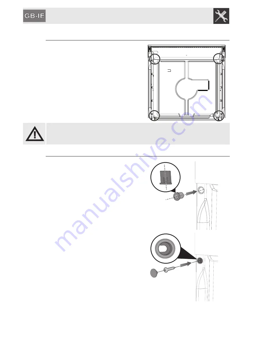
12.3 Inserting the fastening bushings

To fasten the appliance correctly to the
unit, insert the bushings provided onto
the front (as shown in the figure).

Once the appliance is in place, fasten it
to the unit using the screws. The
bushing enables the screw to be
angled by approximately 30°.
After fastening the appliance, cover the
bushing with the caps provided.

Summary of Contents for SC388X-8

Page 1: ...r the qualified technician who must perform the installation put it into operation and test the appliance 1 INSTRUCTIONS FOR USE 54 2 SAFETY PRECAUTIONS 56 3 ENVIRONMENTAL RESPONSIBILITY 58 4 GET TO KNOW YOUR OVEN 59 5 AVAILABLE ACCESSORIES 60 6 FRONT PANEL 63 7 ELECTRONIC ANALOGUE CLOCK 67 8 USING THE OVEN 75 9 COOKING WITH THE OVEN 77 10 CLEANING AND MAINTENANCE 86 11 EXTRAORDINARY MAINTENANCE 9...

Page 2: ...HIS APPLIANCE HAS BEEN MANUFACTURED TO COOK FOOD DO NOT USE THE APPLIANCE TO HEAT ROOMS THIS APPLIANCE IS MARKED ACCORDING TO EUROPEAN DIRECTIVE 2002 96 EC ON WASTE ELECTRICAL AND ELECTRONIC EQUIPMENT WEEE THIS GUIDELINE IS THE FRAME OF A EUROPEAN WIDE VALIDITY OF RETURN AND RECYCLING ON WASTE ELECTRICAL AND ELECTRONIC EQUIPMENT NEVER OBSTRUCT THE OPENINGS AND SLITS PROVIDED FOR VENTILATION AND HE...

Page 3: ...N COULD MELT THE PLASTIC DAMAGING THE APPLIANCE DO NOT USE SEALED TINS OR CONTAINERS IN THE APPLIANCE OVERPRESSURE MAY OCCUR INSIDE THE CONTAINERS DURING COOKING CREATING A DANGER OF EXPLOSION DO NOT LEAVE THE APPLIANCE UNATTENDED DURING COOKING PROCESSES WHERE FATS OR OILS COULD BE RELEASED FATS AND OILS MAY CATCH FIRE DO NOT COVER THE BOTTOM OF THE OVEN WITH ALUMINIUM OR TINFOIL SHEETS DURING CO...

Page 4: ...HE REGULATIONS IN FORCE THE SOCKET MUST BE ACCESSIBLE AFTER THE APPLIANCE HAS BEEN BUILT IN NEVER DISCONNECT THE PLUG BY PULLING ON THE CABLE IF THE POWER SUPPLY CABLE IS DAMAGED CONTACT THE TECHNICAL SUPPORT SERVICE IMMEDIATELY AND THEY WILL REPLACE IT IT IS OBLIGATORY FOR ALL ELECTRICAL EQUIPMENT TO BE EARTHED ACCORDING TO THE METHODS LAID DOWN BY SAFETY REGULATIONS IMMEDIATELY AFTER INSTALLATIO...

Page 5: ...ETS FOR CLEANING THE APPLIANCE THE STEAM COULD REACH THE ELECTRONICS DAMAGING THEM AND CAUSING SHORT CIRCUITS DO NOT MODIFY THIS APPLIANCE DO NOT SPRAY ANY SPRAY PRODUCTS NEAR THE ELECTRICAL APPLIANCE WHILE IT IS IN OPERATION DO NOT USE SPRAY PRODUCTS WHILE THE PRODUCT IS STILL HOT The manufacturer declines all responsibility for damage to persons or things caused by the non observance of the abov...

Page 6: ...t by the user results in the application of administrative sanctions The product does not contain substances in quantities that may be considered a danger to health or the environment in compliance with current European directives 3 2 Your environmental responsibility Our product s packing is made of non polluting materials therefore compatible with the environment and recyclable Please help by di...

Page 7: ...GET TO KNOW YOUR OVEN MULTIFUNCTION PYROLYTIC Control panel Roof liner Oven light Self cleaning side panels Insert for the rotisserie rod Oven fan Rack and tray support frames Oven seal 250 230 200 50 120 160 ECO P 90 8 7 4 6 2 1 5 3 ...

Page 8: ...ting fat from foods placed on the rack above Deep oven tray for baking cakes pizza and oven desserts Rotisserie frame on some models only supports the rotisserie rod Rotisserie rod on some models only for cooking chicken and all foods which require uniform cooking over their entire surface Accessories available on request Original supplied and optional accessories may be ordered from any Authorise...

Page 9: ...w To take it out lift the front edge of the rack slightly while sliding it out on the side runners The mechanical lock or the skirt where present must always face the back of the oven Insert racks and trays fully into the oven until they come to a stop 5 2 Using the support rack The support rack is inserted into the tray as shown in the figure Using this foods can be cooked and the fat can be coll...

Page 10: ...s shown in the figure Then prepare the rotisserie rod with the food using the clip forks provided So that you can handle the rod with the food on it readily screw on the handle provided Having prepared the rotisserie rod with the food position it on the guide frame as shown in the figure Insert the rod into the hole detail B so that it connects with the rotisserie motor Make sure that the pin is p...

Page 11: ...6 FRONT PANEL All the controls and indicator lights can be seen on the front panel The tables below describe the symbols used MULTIFUNCTION PYROLYTIC 3 5 1 1 2 3 4 5 250 230 200 90 120 160 250 230 200 50 120 160 ECO P 90 1 2 3 4 5 ...

Page 12: ...red setting between 50 and 250 This knob also enables the temperature to be selected for Vapor Clean on some models only and for the grill function on some models only When the transparent section displaying the set temperature lights up it means that the oven is heating up When it goes out the preset heating temperature has been reached When the light flashes regularly it means that the temperatu...

Page 13: ...odels the light switches on when the automatic cleaning cycle pyrolysis starts and remains lit until the cycle is complete ELECTRONIC ANALOGUE CLOCK TIMER BUTTON END OF COOKING BUTTON CLOCK ADJUSTMENT AND RESET VALUE DECREASE BUTTON VALUE INCREASE BUTTON FUNCTION DOOR LOCK INDICATOR LIGHT GREEN on some models only In multifunction models this green light comes on when any function is selected usin...

Page 14: ...mer switches off the oven automatically at the end of cooking If no cooking time is selected the timer knob must be positioned on To set the cooking time turn the knob clockwise until it reaches the 90 position and then set the desired cooking time The numbers from 5 to 90 correspond to minutes Adjustment is progressive so that the time can also be set to any intermediate value between these numbe...

Page 15: ... flashes at regular intervals Press for 1 2 seconds to stop the display flashing and start the procedure for setting the correct time Press the value modification keys or to increase or decrease the setting by one minute for each pressure Press one of the two value modification keys until the current time appears 6 7 seconds after the last key is pressed the clock will start from the time set At t...

Page 16: ... representing 1 minute of cooking time will light up or go out figure 2 shows a cooking time of 10 minutes 6 7 seconds after the last key is pressed the countdown will start when it finishes the buzzer will sound During the countdown the current time can be viewed by pressing once press it again to return to the timer display At the end of the countdown the oven must be switched off manually by tu...

Page 17: ...s obtained cooking will start about 6 seconds after the last pressure on or Once cooking has started the display will show the current time represented by the constantly illuminated segments and the minutes left to the end of the cooking time represented by the flashing segments each flashing segment means 12 minutes of cooking time left 1 2 At the end of the cooking time the timer will switch the...

Page 18: ...ime reaches the set starting time all the inside segments will start to flash indicating that the oven has started cooking At the end of the cooking time the timer will switch the oven heating elements off the buzzer will start to sound and the numbers on the dial will flash To reset the whole set program keep the central key pressed for 1 or 2 seconds if cooking has already started the oven will ...

Page 19: ... same procedure 7 2 Operation of the electronic analogue clock in pyrolytic models 7 2 1 Setting the time When the oven is used for the first time or after an interruption in the electricity supply the display flashes at regular intervals Press and at the same time hold down the value modification keys or to set the current time Each individual pressure increases or decreases the time by one minut...

Page 20: ...ws a countdown of 2 hours and 40 minutes 1 2 A few seconds after the last pressure the countdown will start and at the end a buzzer will sound During the countdown the current time can be displayed by pressing After a few seconds the display will go back to showing the countdown The timer duration can be modified at any time by pressing and holding and pressing or again The countdown can be cancel...

Page 21: ...e that the duration has passed 60 minutes For example figure 2 shows a cooking time of 2 hours and 40 minutes 1 2 A few seconds after the last pressure the programmed cooking process will start and at the end a buzzer will sound At the end of the cooking time the timer will switch the oven heating elements off the buzzer will start to sound and the numbers on the display will start to flash The bu...

Page 22: ...l switch the oven heating elements off the buzzer will start to sound and the numbers on the dial will flash To reset the whole set program keep the central key pressed for a few seconds if cooking has already started the oven will have to be switched off manually At the end of the programmed cooking time the oven must be reset to manual by pressing for a few seconds Warning for the oven to start ...

Page 23: ...e empty appliance to the maximum temperature in order to remove any manufacturing residues which could affect the food with unpleasant odours 8 2 General Description 8 2 1 Oven runners The oven features 5 runners for positioning trays and racks at different heights The insertion heights are indicated from the bottom upwards see figure When using the recipes the display will show the recommended ru...

Page 24: ...age the enamel coating If you wish to use greaseproof paper place it so that it will not interfere with the hot air circulation inside the oven For the best cooking results we recommend placing cookware in the centre of the rack To prevent any steam in the oven from causing problems open the door in two stages half open 5 cm approx for 4 5 seconds and then fully open If you need to access the food...

Page 25: ...the cooking of foods that require a greater basic temperature without affecting their browning Perfect for cakes pies tarts and pizzas GRILL The heat coming from the grill element gives perfect grilling results especially for thin and medium thickness meat and in combination with the rotisserie when present it allows the food to be browned evenly at the end of cooking Perfect for sausages ribs and...

Page 26: ...n FAN ASSISTED BOTTOM The combination of the fan with just the lower heating element allows cooking to be completed more rapidly This system is recommended for sterilising or for finishing off the cooking of foods which are already well cooked on the surface but not inside which therefore need a little more heat Perfect for any type of food In pyrolytic models the special defrosting and proving fu...

Page 27: ...eating the oven before putting the food in For cooking on several levels we recommend using a fan assisted function to achieve uniform cooking at all heights In general it is not possible to shorten the cooking times by increasing the temperature the food could be well cooked on the outside and undercooked on the inside While cooking desserts or vegetables excessive condensation may form on the gl...

Page 28: ... next occasion reduce the set temperature by about 10 C selecting a longer cooking time if necessary 9 1 4 Advice for defrosting and proving We recommend positioning frozen foods in a lidless container on the first runner of the oven The food must be defrosted without its wrapping Lay out the foodstuffs to be defrosted evenly not overlapping When defrosting meat we recommend using a rack positione...

Page 29: ...e time normally used Cooking will continue for the remaining minutes with the heat which has accumulated inside the oven Reduce any opening of the door to a minimum to avoid heat dispersal Use the ECO function on some models only for cooking small quantities of food Keep the inside of the appliance clean at all times 9 3 Defrosting function on some models only In multifunction models the defrostin...

Page 30: ...isted static SHOULDER OF PORK 1 kg Turbo ROAST RABBIT 1 kg Circular TURKEY BREAST 1 kg Fan assisted static ROAST NECK OF PORK 1 kg Turbo ROAST CHICKEN 1 kg Turbo GRILLED MEATS PORK CHOPS Fan assisted grill FILLET OF PORK Grill FILLET OF BEEF Grill LIVER Fan assisted grill SAUSAGES Fan assisted grill MEAT BALLS Grill ROTISSERIE MEATS CHICKEN Rotisserie grill FISH SALMON TROUT 0 7 kg Fan assisted bo...

Page 31: ...2 220 230 40 2 180 190 70 80 2 180 190 70 80 2 180 190 90 100 2 180 190 70 80 2 180 190 110 120 2 180 190 190 210 2 190 200 60 70 1ST SURFACE 2ND SURFACE 4 250 280 7 9 5 7 3 250 280 9 11 5 9 3 250 280 9 11 9 11 4 250 280 2 3 2 3 3 250 280 7 9 5 6 3 250 280 7 9 5 6 On a rotisserie rod 250 280 60 70 2 160 170 35 40 ...

Page 32: ...atic SHORT PASTRY Circular JAM TARTS Turbo PARADISE CAKE Fan assisted static PARADISE CAKE Static ECLAIR Turbo LIGHT SPONGE CAKE Circular RICE PUDDING Turbo RICE PUDDING Static CROISSANTS Circular APPLE PIE Static CROISSANTS on multiple runners SHORT PASTRY BISCUITS on multiple runners The times indicated in the following tables do not include the preheating times and are provided as a guide only ...

Page 33: ... TIME IN MINUTES 1 250 280 6 10 2 190 200 25 30 2 180 190 15 20 2 160 55 60 2 160 30 35 2 170 35 40 2 160 170 20 25 2 160 20 25 2 160 55 60 2 170 50 60 2 150 160 40 50 2 150 160 45 50 2 160 40 50 2 170 50 60 2 160 25 30 3 180 60 2 and 4 160 170 16 20 2 and 4 160 170 16 20 ...

Page 34: ... surface rinse thoroughly and dry with a soft cloth or chamois leather 10 3 Food stains or residues Do not use metallic sponges or sharp scrapers as they will damage the surface Use normal non abrasive products and a wooden or plastic tool if necessary Rinse thoroughly and dry with a soft cloth or chamois leather Do not allow residues of sugary foods such as jam to set inside the oven If left to s...

Page 35: ...ts Clean the oven racks with hot water and non abrasive detergent Rinse and dry For easier cleaning the door can be removed see 11 2 Removing the door The oven should be operated at the maximum heat setting for 15 20 minutes after use of specific products to burn off the residues left inside the oven When the operation is complete damp parts should be dried thoroughly ...

Page 36: ... automatic high temperature cleaning procedure which causes dirt to dissolve Thanks to this process it is possible to clean the inside of the oven with great ease During the first automatic cleaning cycle unpleasant smells may occur due to the normal evaporation of oily manufacturing substances This is an absolutely normal phenomenon which disappears after the first cleaning cycle Before starting ...

Page 37: ...ning the door glazing before starting the automatic cleaning cycle For very stubborn encrustations lock the door using the pins provided and remove the glass panel Spray an oven cleaning product onto the glass read the warnings on the product leave for 60 minutes then rinse and dry the glass using kitchen roll or a microfiber cloth After carrying out these operations position the glass panel on th...

Page 38: ...ill start flashing and will become steady once the oven has reached an internal temperature of approx 470 C The door lock light will come on and remain lit until the end of the automatic cleaning cycle The door lock will be activated within approx 1 minute 30 seconds after the last action by the user shown by the relevant light coming on and the number 12 flashing on the display When pyrolysis beg...

Page 39: ...he dirt residues are softened by the heat and water vapour for an easier removal afterwards Before starting the assisted cleaning cycle make sure that the oven does not contain any foods or large spills from previous cooking operations Carry out assisted oven cleaning operations only when the oven is cold 10 8 1 Before starting the assisted cleaning cycle Completely remove all accessories from ins...

Page 40: ...e cavity Spray a water and washing up liquid solution inside the oven using a spray nozzle Direct the spray against the side walls roof base and deflector At the end of this process close the door and set the cleaning cycle Do not spray excessive amounts of the water and washing up liquid solution We recommend spraying approx 20 times at the most ...

Page 41: ...in 7 1 3 Programming The assisted cleaning cycle will start approx 6 seconds after the user last makes a setting change to the electronic analogue clock At the end of the assisted cleaning cycle the timer will deactivate the oven heating elements the buzzer will start to sound and the numbers on the dial will flash Models with timer knob Turn the oven function knob and the oven thermostat knob to ...

Page 42: ...tch sponge with brass filaments on tougher encrustations We recommend removing the door as described in 11 2 Removing the door to facilitate access to restricted spaces If the VAPOR CLEAN cycle is activated after fatty cooking processes meat in particular it may be necessary to use an oven cleaning product at the end of the cycle to completely remove any stubborn residue For improved hygiene and t...

Page 43: ...ault contact your local technical support centre 11 1 Replacing the light bulb If a light bulb needs to be replaced because it is worn or burnt out remove the guide frames see 10 6 Removing guide frames Then remove the bulb cover using a tool e g a screwdriver Remove the bulb by sliding it out as shown On some models only the bulbs are halogen bulbs so do not touch them directly with your fingers ...

Page 44: ... the back of them until they engage Grasp the door on both sides with both hands lift it forming an angle of around 30 and remove it To reassemble the door put the hinges in the relevant slots in the oven making sure that the grooved sections C are resting completely in the slots Lower the door and once it is in place remove the pins from the holes in the hinges ...

Page 45: ... kept thoroughly clean To facilitate cleaning it is possible to remove the door see 11 2 Removing the door and place it on a canvas or open it and lock the hinges in order to extract the glass panels The glass panels of the door can be completely removed by following the instructions provided below Warning before removing the glass panels make sure that at least one of the door s hinges has been l...

Page 46: ...small locks Remove the middle panes by lifting them upwards Multifunction models An intermediate glass panel may be present on multifunction models if so remove it by lifting it upwards Cleaning Now it is possible to clean the external glass panel and the panels removed previously Use absorbent kitchen roll In the case of stubborn dirt wash with a damp sponge and neutral detergent Replacing the gl...

Page 47: ...ection install a multipolar cut out device on the power supply line in accordance with the installation rules located near the appliance and in an easily reachable position If a plug and socket connection is being used make sure that the plug and socket are compatible Avoid use of adapters and shunts as these could cause overheating and risk of burns Operation at 220 240 V use a H05V2V2 F type thr...

Page 48: ...low the best route in order to avoid any contact with the oven WARNING The tightening torque of the screws of the terminal supply wires must be 1 5 2 Nm 12 3 Inserting the fastening bushings To fasten the appliance correctly to the unit insert the bushings provided onto the front as shown in the figure Once the appliance is in place fasten it to the unit using the screws The bushing enables the sc...

Page 49: ...ure as long as it is heat resistant The adjacent figure shows the indicative overall dimensions of the appliance For installing under a work top follow the dimensions given in paragraph 12 4 1 Positioning under a work top When installing in tall units comply with the dimensions shown in paragraph 12 4 2 Installing in tall units bearing in mind that the top rear of the unit must have an opening app...

Page 50: ...Instructions for the installer 102 12 4 1 Positioning under a work top 12 4 2 Installing in tall units ...

Reviews: