background image


QuickServer Start-Up Guide 

Page 42 of 43 

Appendix C.5. Specifications 


FS-QS-2XX0-XXXX 

2


Electrical Connections


One 3-pin Phoenix connector with:  RS-485/RS-232 (Tx+ / Rx- / gnd) 
One 3-pin Phoenix connector with:   RS-485 (Tx+ / Rx- / gnd) 
One 3-pin Phoenix connector with:   Power port (+ / - / Frame-gnd) 
One Ethernet 10/100 BaseT port 

Power Requirements 

Input Voltage:

 9-30VDC or 24VAC 

Current draw:

  24VAC 0.125A 

Max Power:

 3 Watts 

9-30VDC 0.25A @12VDC 

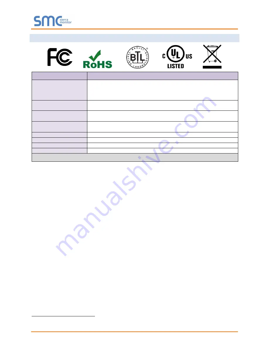
Approvals 

CE and FCC Class B & C Part 15, UL 60950-1, WEEE compliant,  
IC Canada, RoHS3 compliant 

Capacity Options 

FS-QS-20X0: 250 data points 

FS-QS-22X0: 3,000 data points 

FS-QS-23X0: 500 data points 

FS-QS-24X0: 5,000 data points 

Physical Dimensions 

4 x 1.1 x 2.7 in (10.16 x 2.8 x 6.8 cm) 

Weight 

0.4 lbs (0.2 Kg) 

Operating Temperature  

-20°C to 70°C (-4°F to158°F) 

Humidity 

10-95% RH non-condensing 

Figure 34: Specifications 

“This device complies with part 15 of the FCC Rules. Operation is subject to the following two conditions:  


This device may not cause harmful interference. 


This  device  must  accept  any  interference  received,  including  interference  that  may  cause 
undesired operation. 

NOTE:

 This equipment has been tested and found to comply with the limits for a Class A digital device, 

pursuant to part 15 of the FCC Rules. These limits are designed to provide reasonable protection against 
harmful interference when the equipment is operated in a commercial environment. This equipment 
generates, uses, and can radiate radio frequency energy and, if not installed and used in accordance with 
the instruction manual, may cause harmful interference to radio communications. Operation of this 
equipment in a residential area is likely to cause harmful interference in which case the user will be 
required to correct the interference at his expense. Modifications not expressly approved by FieldServer 
could void the user's authority to operate 

the equipment under FCC rules.” 


2


Specifications subject to change without notice.


Summary of Contents for FieldServer QuickServer FS-QS-2 0 Series

Page 1: ...Document Revision 1 L T18627 FieldServer QuickServer Start up Guide FS QS 2XX0 APPLICABILITY EFFECTIVITY Effective for all systems manufactured after July 2020 ...

Page 2: ...nical support needs related to the FieldServer product MSA Safety 1991 Tarob Court Milpitas CA 95035 Website www sierramonitor com U S Support Information 1 408 964 4443 1 800 727 4377 Email smc support msasafety com EMEA Support Information 31 33 808 0590 Email smc support emea msasafety com ...

Page 3: ...ion 19 7 4 Load the Updated Configuration File 20 7 4 1 Using the FS GUI to Load a Configuration File 20 7 4 2 Retrieve the Configuation File for Modification or Backup 21 7 5 Test and Commission the QuickServer 22 7 5 1 Accessing SMC Cloud 22 Appendix A Useful Features 23 Appendix A 1 SSL TLS for Secure Connection 23 Appendix A 1 1 Configuring FieldServer as a SSL TLS Server 23 Appendix A 1 1 1 S...

Page 4: ...tings 35 Appendix B 7 1 User Management 35 Appendix B 7 1 1 Create Users 36 Appendix B 7 1 2 Edit Users 37 Appendix B 7 1 3 Delete Users 38 Appendix B 7 2 Change FieldServer Password 39 Appendix C Reference 40 Appendix C 1 QuickServer FS QS 2XX0 XXXX DCC 40 Appendix C 2 QuickServer Part Numbers 40 Appendix C 3 Compliance with UL Regulations 41 Appendix C 4 Dimension Drawing FS QS 2XX0 XXXX 41 Appe...

Page 5: ... 14 Security Mode Selection Screen Certificate Private Key 16 Figure 15 FS GUI Landing Page 17 Figure 16 FS GUI Network Settings 18 Figure 17 FS GUI File Transfer 19 Figure 18 FS GUI Loading Files 20 Figure 19 Retrieve Configuration File 21 Figure 20 FS GUI Connections Page 22 Figure 21 Ethernet Port Location 29 Figure 22 Diagnostic LEDs 31 Figure 23 FS GUI Page 32 Figure 24 FS GUI Security Setup ...

Page 6: ...vailable on the USB drive provided in the optional accessory kit or on the Sierra Monitor website Accessory kit optional Part FS 8915 38 QS includes 7 ft Cat 5 cable with RJ45 connectors at both ends Power Supply 110 220V p n 69196 Screwdriver for connecting to terminals USB Flash drive loaded with o QuickServer 2XX0 Start up Guide o FieldServer Configuration Manual o All FieldServer Driver Manual...

Page 7: ...43 4 QUICKSERVER SETUP 4 1 Mounting The QuickServer can be mounted using the DIN rail mounting bracket on the back of the unit NOTE For dimension details see Appendix C 4 Figure 1 DIN Rail Bracket Din Rail Bracket Figure 2 DIN Rail Mounted ...

Page 8: ...bias resistor is 510 ohms which is in line with the BACnet spec It should only be enabled at one point on the bus for example on the field port were there are very weak bias resistors of 100k Since there are no jumpers many QuickServers can be put on the network without running into the bias resistor limit which is 500 ohms NOTE See www ni com support serial resinfo htm for additional pictures and...

Page 9: ...ure 4 Termination resistor is also used to reduce noise It pulls the two lines of an idle bus together However the resistor would override the effect of any bias resistors if connected NOTE The R1 and R2 DIP Switches apply settings to the respective serial port NOTE If the gateway is already powered on DIP switch settings will not take effect unless the unit is power cycled R1 Termination Resistor...

Page 10: ...ay Pin Assignment BMS RS 232 Wiring Gateway Pin Assignment RS 485 TX RS 232 TX RS 485 RX RS 232 RX GND GND GND GND NOTE Use standard grounding principles for GND 4 3 2 Supported RS 485 Baud Rates by Protocol The supported baud rates for either port is based on the protocol of the connected devices The following baud rates are supported for Modbus RTU 2400 4800 9600 19200 38400 57600 76800 115200 T...

Page 11: ...e added to the power supply of the host system A safety margin of 25 is recommended Figure 6 Required Current Draw for the Gateway Apply power to the QuickServer as shown below in Figure 7 Ensure that the power supply used complies with the specifications provided in Appendix C 5 The QuickServer accepts 9 30VDC or 24VAC on pins L and N Frame GND should be connected Power to Gateway Gateway Pin Lab...

Page 12: ...l Panel click Network and Internet and then click Network and Sharing Center Click Change adapter settings on the left side of the window Right click on Local Area Connection and select Properties from the dropdown menu Highlight and then click the Properties button Select and enter a static IP Address on the same subnet For example Click the Okay button to close the Internet Protocol window and t...

Page 13: ...ntrusted This will cause the following pop up windows to appear When the Web Server Security Unconfigured window appears read the text and choose whether to move forward with HTTPS or HTTP When the warning that Your connection is not private appears click the advanced button on the bottom left corner of the screen Figure 10 Connection Not Private Warning Figure 9 Web Server Security Unconfigured W...

Page 14: ...e default is admin and the Password found on the label of the FieldServer NOTE There is also a QR code in the top right corner of the FieldServer label that shows the default unique password when scanned NOTE A user has 5 attempts to login then there will be a 10 minute lockout There is no timeout on the FieldServer to enter a password NOTE To create individual user logins go to Appendix B 7 Figur...

Page 15: ...ll appear that allows the user to select which mode the FieldServer should use NOTE Cookies are used for authentication NOTE To change the web server security mode after initial setup go to Appendix B 6 The sections that follow include instructions for assigning the different security modes Figure 13 Security Mode Selection Screen ...

Page 16: ...into their respective fields If the Private Key is encrypted type in the associated Passphrase Click Save A Redirecting message will appear After a short period of time the FieldServer GUI will open 6 2 2 HTTPS with Default Untrusted Self Signed TLS Certificate or HTTP with Built in Payload Encryption Simply select one of these options and click the Save button A Redirecting message will appear Af...

Page 17: ...utton see Figure 15 allows users to connect to the SMC Cloud MSA Safety s device cloud solution for IIoT The SMC Cloud enables secure remote connection to field devices through a FieldServer and its local applications for configuration management maintenance For more information about the SMC Cloud refer to the SMC Cloud Start up Guide Figure 15 FS GUI Landing Page ...

Page 18: ...ver should be set to the same IP Address of the router Click Update IP Settings then click on the System Restart to restart the Gateway and activate the new IP Address NOTE If the FS GUI was open in a browser the browser will need to be pointed to the new IP Address of the QuickServer before the FS GUI will be accessible again NOTE The SMC Cloud button see Figure 16 allows users to connect to the ...

Page 19: ...egisters in the Config csv file for the initial start up If not the product is shipped with a sample config csv that shows an example of the drivers ordered In the main menu of the FS GUI screen go to Setup then File Transfer and finally Retrieve Click on config csv and open or save the file 7 3 Change the Configuration File to Meet the Application Refer to the FieldServer Configuration Manual in ...

Page 20: ...then File Transfer and finally Update Browse and select the csv file open then click Submit Once download is complete a message bar will appear confirming that the configuration was updated successfully Click the System Restart Button to put the new file into operation NOTE It is possible to do multiple downloads to the QuickServer before resetting it Figure 18 FS GUI Loading Files ...

Page 21: ...n menu of the FS GUI screen click Setup then File Transfer Click the config csv link under the Retrieve heading in the middle section of the screen o The file will automatically download to the web browser s default download location Edit or store the file as desired NOTE Before using any backup configuration file to reset the configuration settings check that the backup file is not an old version...

Page 22: ...e the number of messages on each protocol 7 5 1 Accessing SMC Cloud The SMC Cloud button see Figure 16 allows users to connect to the SMC Cloud MSA Safety s device cloud solution for IIoT The SMC Cloud enables secure remote connection to field devices through a FieldServer and its local applications for configuration management maintenance For more information about the SMC Cloud refer to the SMC ...

Page 23: ...ver Configuration Add TLS_Port parameter in the connections section of the configuration file and set to a port number between 1 65535 Connections Adapter Protocol TLS_Port N1 Modbus TCP 1502 This configuration sets the FieldServer to accept any incoming connection but will not request a client s certificate for verification This means that the FieldServer end point communication will be encrypted...

Page 24: ...ver with the following connection settings Connections Adapter Protocol TLS_Port Validate_Client_Cert Cert_Authority_File N1 Modbus TCP 1502 Yes my_authorized_clients pem This configuration has the FieldServer accept connections from clients who have the correct certificate The authority file is a collection of client certificates in PEM format This file can be edited using any text file editor NO...

Page 25: ...nymously known as common name host name or domain etc The common name can be obtained by the following methods Ask the certificate issuer for the host name Use online tools to decode the certificate for example https www sslshopper com certificate decoder html If the program openssl is installed on the local PC then run the following command to get the common name openssl x509 in certificate pem t...

Page 26: ...ertificate against its own internal authority file before finalizing the connection By default this means the FieldServer will only establish connections to other FieldServers Remote_Node_TLS_Port Validate_Server_Cert Cert_Authority_File 1502 Yes my_authorized_servers pem The above configuration sets the FieldServer to use a specified PEM file to allow custom server connections The authority file ...

Page 27: ... the PC s Device Manager List and that it is configured to run the TCP IP protocol Check that the IP netmask of the PC matches the QuickServer The Default IP Address of the QuickServer is 192 168 2 X Subnet Mask is 255 255 255 0 o Go to Start Run o Type in ipconfig o The account settings should be displayed o Ensure that the IP Address is 102 168 2 X and the netmask 255 255 255 0 Ensure that the P...

Page 28: ...r Diagnostics page via one of the following methods o Open the FieldServer FS GUI page and click on Diagnostics in the Navigation panel o Open the FieldServer Toolbox software and click the diagnose icon of the desired device Go to Full Diagnostic and select the capture period Click the Start button under the Full Diagnostic heading to start the capture o When the capture period is finished a Down...

Page 29: ...te diagnosis of the problem NOTE While all necessary documentation is shipped with the FieldServer on the USB flash drive these documents are constantly being updated Newer versions may be available on the Sierra Monitor website Ensure that FieldServer Toolbox is loaded onto the local PC Otherwise download the FieldServer Toolbox zip via the Sierra Monitor website s Software Downloads Extract the ...

Page 30: ...ick on the Start Diagnostic button o Wait for the capture period to finish and the Diagnostic Test Complete window will appear Step 2 Send Log o Once the diagnostic test is complete a zip file is saved on the PC o Click Open to launch explorer and have it point directly at the correct folder o Email the diagnostic zip file to smc support msasafety com ...

Page 31: ...ource TX The TX LED will flash when a message is received on the serial port on the 3 pin connector If the serial port is not used this LED is non operational TX1 applies to the R1 connection while TX2 applies to the R2 connection RX The RX LED will flash when a message is sent on the serial port on the 3 pin connector If the serial port is not used this LED is non operational RX1 applies to the R...

Page 32: ...r Safari Rev 3 and higher NOTE Internet Explorer is no longer supported as recommended by Microsoft NOTE Computer and network firewalls must be opened for Port 80 to allow FieldServer GUI to function Appendix B 6 Change Web Server Security Settings After Initial Setup NOTE Any changes will require a FieldServer reboot to take effect From the FS GUI page click Setup in the Navigation panel Figure 2...

Page 33: ...ppendix B 6 1 Change Security Mode Click Security in the Navigation panel Click the Mode desired o If HTTPS with own trusted TLS certificate is selected follow instructions in Section 6 2 1 Click the Save button Figure 24 FS GUI Security Setup ...

Page 34: ... will only be available if the security mode was previously setup as HTTPS with own trusted TLS certificate Click Security in the Navigation panel Click the Edit Certificate button to open the certificate and key fields Edit the loaded certificate or key text as needed Click Save Figure 25 FS GUI Security Setup Certificate Loaded ...

Page 35: ... see the FieldServer Recovery Instructions document For ProtoAir recovery instructions see the FieldServer Next Gen Recovery document If the default unique password is lost then the unit must be mailed back to the factory NOTE Any changes will require a FieldServer reboot to take effect Appendix B 7 1 User Management Check that the Users tab is selected User Types Admin Can modify and view any set...

Page 36: ...oup and Password o User details are hashed and salted NOTE The password must meet the minimum complexity requirements An algorithm automatically checks the password entered and notes the level of strength on the top right of the Password text field Click the Create button Once the Success message appears click OK Figure 27 Create User Window ...

Page 37: ...s Click the pencil icon next to the desired user to open the User Edit window Once the User Edit window opens change the User Security Group and Password as needed Click Confirm Once the Success message appears click OK Figure 28 Setup Users Figure 29 Edit User Window ...

Page 38: ...p Guide Page 38 of 43 Appendix B 7 1 3 Delete Users Click the trash can icon next to the desired user to delete the entry When the warning message appears click Confirm Figure 30 Setup Users Figure 31 User Delete Warning ...

Page 39: ...ments An algorithm automatically checks the password entered and notes the level of strength on the top right of the Password text field NOTE If a gateway in the field is updated to a secure gateway the password will change to admin This change will still occur if the gateway was already setup with a unique password that was loaded in the factory and printed on the label Figure 32 FieldServer Pass...

Page 40: ...dix C 2 QuickServer Part Numbers Field Connections Interface Connections RS 2321 RS 4852 RS 4223 KNX6 RS 485 M Bus Ethernet4 LonWorks5 QuickServer FS QS 2X10 1 2 1 FS QS 2X20 1 2 1 FS QS 1011 1 1 1 FS QS 1211 1 1 1 FS QS 1221 1 1 1 FS QS 1230 1 1 1 FS QS 1231 1 1 1 FS QS 1240 1 1 1 FS QS 1241 1 1 1 FS QS 1A50 1 1 1 FS QS 1A51 1 1 1 FS QS 1B50 1 1 1 FS QS 1B51 1 1 1 FS QS 1C50 1 1 1 FS QS 1C51 1 1 ...

Page 41: ...ing temperature range o Meet the current and voltage rating for QuickServer Net Furthermore the interconnecting power cable shall o Be of length not exceeding 3 05m 118 3 o Be constructed of materials rated VW 1 FT 1 or better If the unit is to be installed in an operating environment with a temperature above 65 C it should be installed in a Restricted Access Area requiring a key or a special tool...

Page 42: ...5 of the FCC Rules Operation is subject to the following two conditions This device may not cause harmful interference This device must accept any interference received including interference that may cause undesired operation NOTE This equipment has been tested and found to comply with the limits for a Class A digital device pursuant to part 15 of the FCC Rules These limits are designed to provid...

Page 43: ...which original identification marks have been removed or altered This Limited Warranty also will not apply to interconnecting cables or wires consumables or to any damage resulting from battery leakage In all cases MSA Safety s responsibility and liability under this warranty shall be limited to the cost of the equipment The purchaser must obtain shipping instructions for the prepaid return of any...

Reviews: