


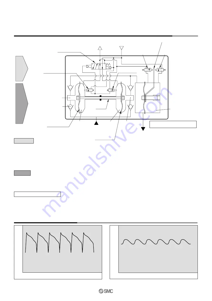
Working Principle: Automatically Operated Type, Built-in Pulsation Attenuator
Drive unit
1. Pulsation is attenuated by the elastic force of the diaphragm and air in the pulsation attenuation chamber.
2. When the pressure in the pulsation attenuation chamber rises, the change lever presses the pulsation attenuator intake valve, and air en-
ters the pulsation attenuator air chamber.
3. Conversely, when pressure drops, the change lever presses the pulsation attenuator exhaust valve, exhausting the air from the air cham-
ber and keeping the diaphragm in a constant position. Note that some time is required for the pulsation attenuator to operate normally.
Pulsation attenuation chamber
Control unit
Switching valve
Pilot valve A
Pilot valve B
Diaphragm A
Drive chamber A
Drive chamber B
Pump chamber B
Check valve
Shaft
Pulsation attenuator
air chamber
Pulsation attenuator unit
Pulsation attenuator
exhaust valve
Pulsation attenuator
intake valve
Change lever
Pump chamber A
Air supply port
(AIR SUP)
Air exhaust port
(AIR EXH)
Discharge port
(FLUID OUT)
Suction port
(FLUID IN)
Control unit
Drive unit
Diaphragm B
Pulsation Attenuating Capacity
With built-in pulsation attenuator
The process pump generates pulsation because it discharges a liquid using two diaphragms. The pulsation attenuator absorbs pressure when
discharge pressure increases, and compensates the pressure when discharge pressure decreases. By this means pulsation is controlled.
0.5
0
0.7
MPa
Without pulsation attenuator
MPa
0.5
0
0.7
1. When air is supplied, it passes through the switching valve and enters drive chamber B.
2. Diaphragm B moves to the right, and at the same time diaphragm A also moves to the right pushing pilot valve A.
3. When pilot valve A is pushed, air acts upon the switching valve, drive chamber A switches to a supply state, and the air which was in
drive chamber B is exhausted to the outside.
4. When air enters drive chamber A, diaphragm B moves to the left pushing pilot valve B.
5. When pilot valve B is pushed, the air which was acting upon the switching valve is exhausted, and drive chamber B once again
switches to a supply state. A continuous reciprocal motion is generated by this repetition.
1. When air enters drive chamber B, the fluid in pump chamber B is forced out, and at the same time fluid is sucked into pump chamber A.
2. When the diaphragm moves in the opposite direction, the fluid in pump chamber A is forced out, and fluid is sucked into pump chamber B.
3. The pressure of the fluid that is forced out of the pump chamber is adjusted in the pulsation attenuation chamber and is then exhausted.
4. Continuous suction/discharge is performed by the reciprocal motion of the diaphragm.
692
Series
PAX1000
Summary of Contents for PA3000 Series
Page 19: ...688 ...