

JXCP1-TF2Z197EN
Page 1 of 2
Instruction Manual
Step Motor Controller - PROFINET
(24 VDC Servo)
Series JXCP1#-#
The intended use of the step motor controller is to control
the movement of an electric actuator while connected to
the PROFINET communication protocol..
1 Safety Instructions
These safety instructions are intended to prevent hazardous situations
and/or equipment damage. These instructions indicate the level of
potential hazard with the labels of “Caution,” “Warning” or “Danger.”
They are all important notes for safety and must be followed in addition
to International Standards (ISO/IEC)
*1)
, and other safety regulations.
IEC 60204-1: Safety of machinery - Electrical equipment of machines.
(Part 1: General requirements)
ISO 10218-1: Robots and robotic devices - Safety requirements for
industrial robots - Part 1: Robots.
•
Refer to product catalogue, Operation Manual and Handling
Precautions for SMC Products for additional information.
•
Keep this manual in a safe place for future reference.
Caution
Caution indicates a hazard with a low level of risk which, if
not avoided, could result in minor or moderate injury.
Warning
Warning indicates a hazard with a medium level of risk
which, if not avoided, could result in death or serious injury.
Danger
Danger indicates a hazard with a high level of risk which, if
not avoided, will result in death or serious injury.
Warning
•
Always ensure compliance with relevant safety laws and
standards.
•
All work must be carried out in a safe manner by a qualified person in
compliance with applicable national regulations.
2 Specifications
2.1 General specifications
Item
Specifications
Compatible motor
Step motor (servo 24 VDC)
Power supply
Power supply voltage: 24 VDC +/-10%
(motor drive control, stop, lock brake release)
Current consumption
200 mA maximum (controller)
Refer to the actuator specifications for total
power consumption.
Compatible encoder
Incremental A/B phase (800 pulse/rotation)
Memory
Eeprom
Lock control
Forced lock release terminal
Cable length
Actuator cable: 20 m maximum
Cooling method
Natural air-cooling
Operating
temperature
0°C to 40°C (version S1.*/S2.*/V1.*/V2.*)
0°C to 55°C (version S3.*/V3.* or later)
No freezing
Storage temperature
-10
o
C to 60
o
C (no freezing)
Operating humidity
90% RH or less (no condensation)
Insulation resistance
50 MΩ (500
VDC)
between external terminals and case
Weight
220 g (Direct mounting type)
240 g (DIN rail mounting type)
2 Specifications (continued)
2.2 PROFINET specifications
Item
Specification
Protocol
PROFINET (Version 2.32)
IP address setting
range
0.0.0.0 to 255.255.255.255
(set using DHCP server)
Communication speed
100 Mbps
Communication
method
Full duplex/ Half duplex (automatic
negotiation)
Communication cable
Standard Ethernet cable
(STP, CAT5 or higher, 100BASE-TX)
Setup file
GSDML file
Occupied area
Input 36 byte / Output 36 byte
Connectable nodes
Max. 65,535 nodes
Vendor ID
83h (SMC Corporation)
Device ID
0Fh
Warning
Special products (-X) might have specifications different from those
shown in this section. Contact SMC for specific drawings.
3 Name and function of individual parts
No.
Name
Description
1
Display
LED to indicate the controller status.
2
PROFINET P1 / P2
Connect to the PROFINET network
3
Serial I/O connector
(8 pin) SI
Connector for the teaching box
(LEC-T1) or the controller
communication cable (JXC-W2A-C).
4
Encoder connector
(16 pin) ENC
Connections for actuator cable.
5
Motor power connector
(6 pin) MOT
6
Power supply
connector
(6 pin) PWR
Connector for controller power
supply (24 VDC) using the power
supply plug.
Control power (+), Stop signal (+),
Motor power (+), Lock release (+),
Common power (-)
7
Applicable electric
actuator model number
label
Label indicating the electric actuator
model number which can be
connected to the controller.
8
Controller label
Label indicating the model number
of the controller.
9
MAC address
Label to indicate MAC address
10
FE connection
Functional Ground
(When the controller is mounted,
tighten screws and connect the
grounding cable).
4 Installation
4.1 Installation
Warning
•
Do not install the product unless the safety instructions have been read
and understood.
•
Design the installation so that the temperature surrounding the
controller is 40
o
C max. Leave enough space between the controllers
so that the operating temperature of the controllers remains within the
specification range.
•
Mount the controller vertically with 30 mm minimum space on the top
and bottom of the controller as shown below.
•
Allow 60 mm minimum space between the front of the controller and a
door (lid) so that the connectors can be connected and disconnected.
4.2 Mounting
•
The controller can be direct mounted (model JXCP17#) using 2 x M4
screws or mounted on a DIN rail (model JXCP18#).
•
When using DIN rail mounting, hook the controller on the DIN rail and
press the lever down to lock it.
Caution
If the mounting surface for the controller is not flat or is uneven, excessive
stress may be applied to the enclosure, which can cause failure. Be sure
to mount on a flat surface.
4.3 Environment
Warning
•
Do not use in an environment where corrosive gases, chemicals, salt
water or steam are present.
•
Do not use in an explosive atmosphere.
•
Do not expose to direct sunlight. Use a suitable protective cover.
•
Do not install in a location subject to vibration or impact in excess of
the product’s specifications.
•
Do not mount in a location exposed to radiant heat that would result in
temperatures in excess of the product’s specifications.
•
Avoid mounting the controller near a vibration source, such as a large
electromagnetic contactor or circuit breaker on the same panel.
•
Do not use in an environment with strong magnetic fields present.
4.4 Wiring
Caution
•
Do not perform wiring while the power is on.
•
Confirm proper insulation of wiring.
•
Do not route wires and cables together with power or high voltage
cables.
•
Keep wiring as short as possible to prevent interference from
electromagnetic noise and surge voltage.
•
Do not use an inrush current limited type of power supply for the
controller.
4 Installation (continued)
•
Do not connect multiple wires to one connector terminal.
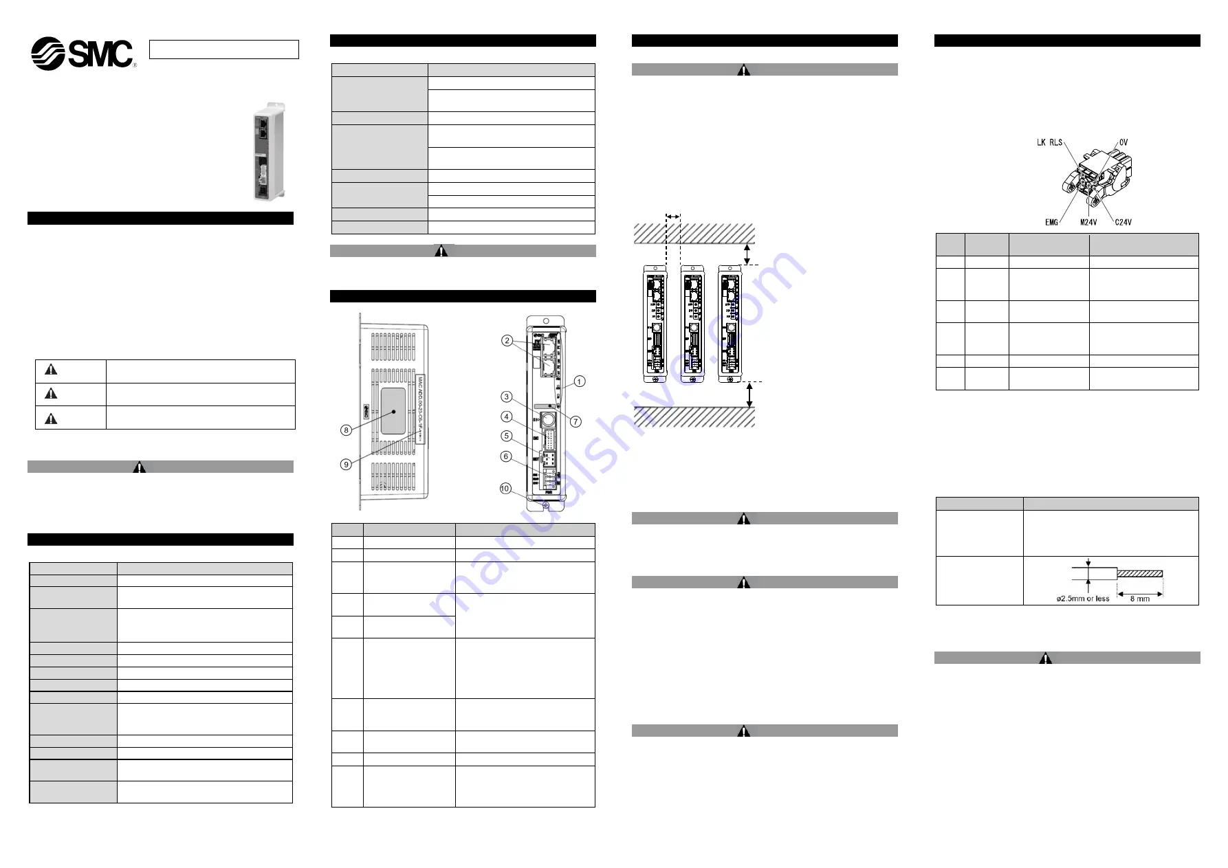
Power Supply Connector
Wire the power supply cable to the power supply plug connector, then
insert it into connector PWR on the controller.
•
Use special screwdriver (Phoenix Contact No. SZS0.4×2.0) to open /
close lever and insert the wire into the connector terminal.
•
Applicable wire size: 20 AWG (0.5 mm
2
).
Pin
No.
Terminal
Function
Description
1
C24V
Power supply (+)
Positive control power.
2
M24V
Motor power (+)
Positive power for the
actuator motor supplied
via the controller.
3
EMG
Stop (+)
Positive power for
emergency stop signal
4
0V
Common power (-)
Negative common power for
M24V, C24V, EMG and LK
RLS.
5
-
NC
Not connected
6
LK RLS
Unlocking (+)
Positive power for lock
release.
Wiring specifications
Prepare the electrical wiring according to the following specifications (to
be prepared by the user).
Item
Specifications
Applicable wire size
Single, stranded wire
→
AWG20 (0.5 mm
2
)
•
The rated temperature of the insulation
coating should be 60
o
C or more.
The O.D. should be ø2.5mm or less.
Stripped wire length
4.5 Ground connection
•
Place a ground cable with crimped terminal under one of the M4
mounting screws with a shakeproof washer and tighten the screw.
Caution
The M4 screw, cable with crimped terminal and shakeproof washer must
be prepared by the user.
The controller must be connected to Ground to reduce noise. If higher
noise resistance is required, ground the 0 V (signal ground). When
grounding the 0 V, avoid flowing noise from ground to 0 V.
•
A dedicated Ground connection must be used. Grounding should be
to a D-
class ground (ground resistance of 100 Ω maximum).
•
The cross-sectional area of the ground cable shall be 2 mm
2
minimum.
•
The Grounding point should be as near as possible to the controller.
Keep the grounding cable as short as possible.
ORIGINAL INSTRUCTIONS
Power supply connector.
SMC Part No. JXC-CPW.
Phoenix Contact Part No:
DFMC1,5/3-ST-LR
30 mm minimum
Controller
10 mm minimum
(for actuator body size 25 mm or more)
30 mm minimum (direct mounting)
50 mm minimum (DIN rail mounting)


