IDX-OM-W025
Air Dryer
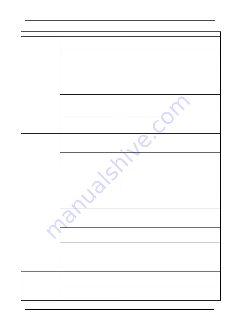
5 Troubleshooting
5-1 Cause and countermeasure of errors
5 - 2
IDF Series
Problem Probable
Causes
Remedy
The evaporation
thermometer is
over the green
area without hot
air coming from
the ventilation
port (exhaust
port).
(The compressor
for refrigeration
has stopped with the
lamp lit up.
The product is installed in an
inappropriate location.
Ambient temperature is excessive.
- Improve ventilation condition and reduce the ambient
temperature as much as possible.
The ventilation port is obstructed by
a wall or clogged with dust.
- Keep the product 600mm or more away from the
surrounding walls.
- Clean the ventilation ports once every month.
The compressed air temperature is
excessive.
- Improve the ventilation in the location where the air
compressor is installed, or decrease the ambient
temperature to allow the discharge air temperature of the
air compressor to go down.
- Install an aftercooler after the air compressor to reduce
the temperature.
The fluctuation of the power supply
voltage is too large.
- Install a power supply transformer or use a different power
supply to provide appropriate voltage.
- The fluctuation of the power supply voltage should be kept
/-10% of the rated voltage.
The built-in overload relay of the
compressor for refrigeration has
started.
- Check the product was not restarted within 3 minutes after
being stopped.
The evaporation
thermometer is
over the green
area with hot air
coming from the
ventilation port
(exhaust port).
The product is installed in an
inappropriate location.
Ambient temperature is excessive.
- Improve ventilation condition and reduce the ambient
temperature as much as possible.
The ventilation port is obstructed by
a wall or clogged with dust.
- Keep the product 600mm or more away from the
surrounding walls.
- Clean the ventilation ports once every month.
The compressed air temperature is
excessive.
- Improve the ventilation in the location where the air
compressor is installed, or decrease the ambient
temperature to allow the discharge air temperature of the
air compressor to go down.
- Install an aftercooler after the air compressor to reduce
the temperature.
Moisture is
generated at the
downstream of
the compressed air
line.
The bypass valve is open.
- Be sure to fully close the bypass valve.
Condensate is not drained from the
auto drain.
-
Check the draining piping is not used in an upward
direction nor bent.
- Check the auto drain.
- Check the auto drain strainer.
The pressure fluctuation (pulsation)
of the compressed air is too high.
-Install an air tank on the primary side of the dryer.
-Avoid intermittent compressed air flow.
Residual drainage in the air dryer
splashes over when the unit is
re-started.
-Install a filter on the outlet of the air dryer.
- Blow the unit by air to eliminate the residual drainage after
stopping or re-starting the operation.
The piping of a different system
without an air dryer joins the piping
after the product.
- Install another air dryer (this product) in that system.
- Keep the two systems separate.
The compressed
air pressure is
too large.
The valves at the inlet and outlet of
the piping of the product are not
fully opened.
- Be sure to fully open the valves at the inlet and outlet of
the product.
The air filter, etc. installed in the
compressed air piping has got
clogged.
- Replace the element of the air filter.
(Follow the Operation Manual of the equipment.)