HRX-OM-R039
Chapter 3 Transport and Setting Up
3.5
Fill of circulating fluid
HRSE Series
3-12
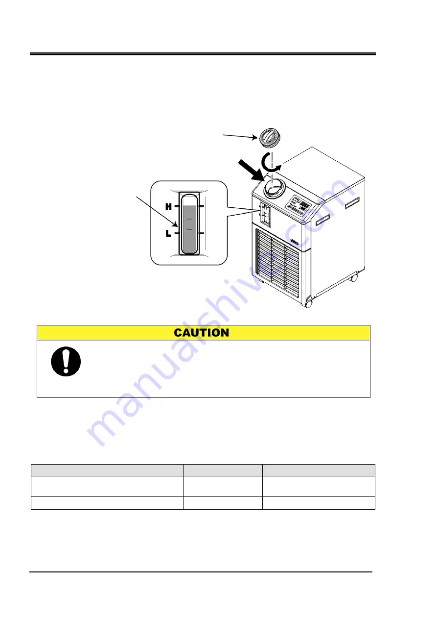
3.5 Fill of circulating fluid
Turn the tank lid anticlockwise to open. Supply the circulating fluid up to the
“H” mark on the fluid level indicator. Use tap water which satisfies the water
quality standard shown inTable 7-1, or a 15% aqueous solution of ethylene
glycol.
Fig. 3.5-1
Circulating fluid fill
15% aqueous solution of ethylene glycol
When a 15% aqueous solution of ethylene glycol is used, prepare the ethylene glycol aqueous
solution separately.
To control the concentration of the ethylene glycol aqueous solution, a concentration meter is available
separately from SMC.
Item
No
Remarks
Ethylene glycol aqueous solution 60%
HRZ-BR001
Please dilute to 15% with tap
water and use it.
Densitometer
HRZ-BR002
-
Tank lid
Circulating fluid fill
Liquid level
Check the drain port is plugged or closed by the valve to prevent the
supplied circulating fluid from draining out.
Supply the circulating fluid up to the “H” mark on the tank.
If the liquid level in the tank becomes lower than the "L" level or the
circulating fluid flow becomes 4L/min or less, the thermo chiller stops
operation.