background image

HRX-OM-J022 

5  Error Message and Troubleshooting


5.2 Troubleshooting 

HRG001-W HRG002-W HRG005-W 

1

st

 edition : Jul. 2005 

5-2  

5.2 Troubleshooting 

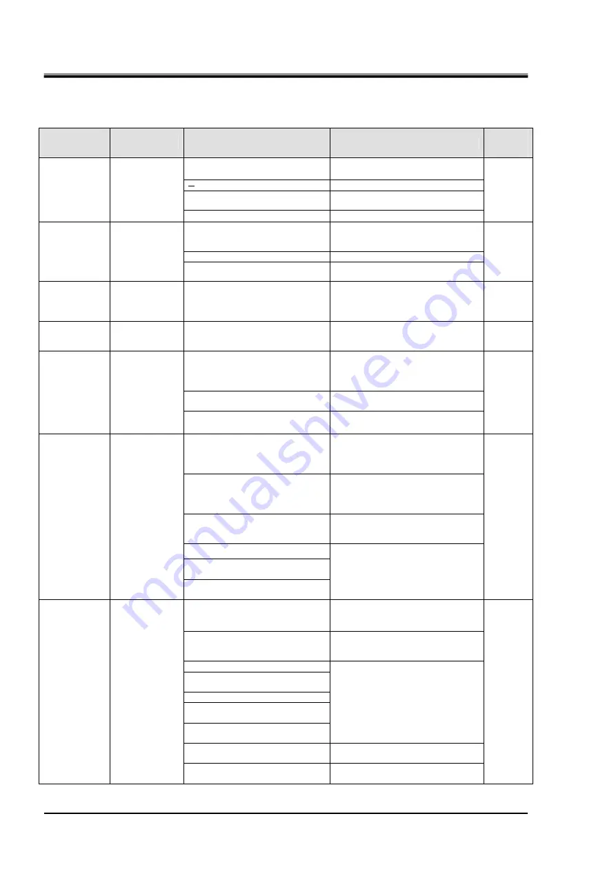
Table 5-2  Troubleshooting 

Alarm 

Unit status 

Cause 

Remedies 

How to 

reset 

Power is not supplied. 

Supply the power. 

A breaker is tripped. 

Fix a short or ground fault. 

Low voltage 

Supply a rated voltage. 

Power error 

The [POWER] 
LED is not 
turned on. 

Failure in the [POWER] LED 

Ask for service. 

Manual 
reset 
 

One of the three-phase power is
interrupted. A voltage sag 
occurred. 

Normal according to product spec. 
Supply three-phase power.   

Failure in the [RUN] LED 

Ask for service. 

Startup failure 

The [RUN] 
LED remains 
off even with 
the press of 
the [ON] 
switch. 

Failure in the [ON] switch 

Ask for service. 

Auto 
reset


Reverse of 
pump and 

compressor


Reverse phase 
relay starts. 

Incorrect phase sequence of   
power wiring 


  Normal according to product spec. 

Rewire the power cable for two of 
three phases. Wiring should be 
performed by a qualified person. 

Auto 
reset


Tank water 
level drop


Level switch 
contact is 
opened. 

Inadequate water in the tank   
(natural evaporation) 

Normal according to product spec. 
Circulating water is low in amount. 
Supply the circulating water.   

Auto 
reset


Power voltage sag 

Normal according to product spec. 

Boost up the capacity of power 
breaker.  Wiring should be 
performed by a qualified person. 

Abnormal rise in circullating fluid 
pressure 

Adjust the opening of the manual 
relief valve. Ask for service. 

Pump 
overload


Pump thermal 

overload 
switch has 
been tripped.   

Abnormal failure of pump 

Change the pump. 
Ask for service. 

Manual 
reset 
 

Power voltage sag 


Normal according to product spec. 
Boost up the capacity of power 
breaker. Wiring should be 
performed by a qualified person. 

Abnormal heat dissipation 

capability of condensor. 

Normal according to product spec. 
Improve ambient conditions to 
provide ventilation and exhaust 
heat.  

Improper rated cooling capability

Normal according to product spec. 
Reduce a calorific value output 
from user’s unit. 

Refrigerant leak 
Abnormal failure in the 
compressor  

Compressor 

overload


Compressor 
thermal 
overload 
switch has 
been tripped.   

Failure in the electromagnetic 
switch 

Ask for service to get the 
refrigerant gas charged and the 
compressor and electromagnetic 
switch replaced. 

Manual 
reset 
 

Rise in ambient temperature 


Improve ambient conditions. Avoid 

installing it at a place exposed to  
direct sunlight or radiant heat. 

Improper rated cooling capability

Normal according to product spec. 
Reduce a calorific value output 
from user’s unit. 

Refrigerant leak 
Failure in the refrigerant solenoid 
valve 
Failure in the compressor   
Other abnormalities in the 
refrigeration circuit 
Failure in the temperature 
controller 

Ask for service to get the 
refrigerant gas charged and the 
compressor and electromagnetic 
switch replaced. 

Over the cooling capability 

Reduce  a  calorific  value  output 
from user’s unit. 

High temp. of 

recirculating 
fluid 

The contact of 
temperature 
controller EV1 
is opened 
 

Abnormal failure of fan motor 

Replace the fan motor. 
Ask for service. 

Auto 
reset 

Summary of Contents for HRG001-A

Page 1: ...st edition Jul 2005 Rev A Sep 2006 Operation Manual Water refrigerated Thermo cooler HRG001 W HRG002 W HRG005 W SMC Corporation Save This Manual Carefully for Use at Any Time 2005 SMC CORPORATION All Rights Reserved ...

Page 2: ...nual are qualified to perform the installation and operation of the unit This manual attached to the unit and its contents will not be a part of contract and accompany modification or change of existing agreement commitment or relation All SMC s obligation is covered by Sales Agreement which is only document to guarantee the content described on the agreement Any description of this manual will no...

Page 3: ... 1 7 1 5 1 Recovery of refrigerant and compressor oil 1 7 1 5 2 Disposal of unit 1 7 2 Descriptions of Components 2 1 2 1 APPEARANCE OF UNIT 2 1 2 1 1 HRG001 W HRG002 W 2 1 2 1 2 HRG005 W 2 1 2 2 DESCRIPTIONS AND FUNCTIONS OF COMPONENTS 2 2 2 2 1 HRG001 W HRG002 W 2 2 2 2 2 HRG005 W 2 3 2 2 3 Control panel 2 4 3 Transport and Installation 3 1 3 1 TRANSPORT 3 1 3 2 INSTALLATION 3 3 3 2 1 Installati...

Page 4: ...ing the unit 4 4 4 4 CHECK AT STARTUP 4 5 5 Error Message and Troubleshooting 5 1 5 1 ERROR MESSAGE 5 1 5 2 TROUBLESHOOTING 5 2 6 Unit Maintenance 6 1 6 1 CONTROL OF WATER QUALITY 6 1 6 2 INSPECTION AND CLEANING 6 2 6 2 1 Daily inspection 6 3 6 2 2 Monthly inspection 6 4 6 2 3 Biannual inspection 6 4 6 3 STORAGE 6 5 6 4 CONSUMABLES 6 5 7 Documents 7 1 7 1 SPECIFICATIONS LIST 7 1 7 2 OUTLINE DIMENS...

Page 5: ...derstand the safety related items in this manual before working with this unit z This manual is not for comprehensive safety and hygiene education Such a manual should be provided by a safety training manager z All personnel who work on or around this unit are to have proper training and education on dangers specific to this unit and safety measures against potential hazards z A safety manager is ...

Page 6: ...us injury and minor injury Serious injury This term describes injuries such as loss of eyesight wound burns electrical shock fracture toxication that leaves aftereffects which may require prolonged treatment and hospitalization Minor injury This term describes injuries that do not require prolonged treatment or hospitalization injuries other than serious injuries described above DANGER means that ...

Page 7: ...ls in easy to understand manner Symbol of electrical hazard Symbol of heat hazard Symbol of rotating shaft hazard Symbol of Don ts Symbol of Dos This symbol denotes the items that must not be implemented This symbol denotes the obligation items which you must follow in operation of this unit This symbol warns you of possible risk of electrical shock This symbol warns you of potential burns This sy...

Page 8: ...may cause the operator to get the finger caught in these parts The attached label contains the symbol Do not operate the unit without the cover panel mounted The unit contains the power supply carrying high voltage inside that is isolated with the cover panel Unit operation without the cover panel allows the high votage to apply outside and cause injuries Only trained personnel are allowed to work...

Page 9: ...05 1 5 1 3 2 Type of hazard warning labels Warning label on the front panel Fig 1 1 Warning label on the front panel Warning label for high voltage Fig 1 2 Warning label for high voltage Do not remove or deface the warning labels Read the contents of the hazard warning labels with care to keep them in mind ...

Page 10: ...rning label 1 4 Model label Check the model no described on the label Fig 1 4 Location of model label Front Warning label for high voltage Warning label on the front panel z Recognize where the hazard warning labels are attached z The user is not allowed to reposition the labels If the label is replaced due to being peeled off or worn out keep the previous position Front ...

Page 11: ... laws and regulations Remarks The type and amount of used freon can be found on the label Only service personnel or qualified personnel are allowed to open the cover panel of the unit Only personnel with sufficient knowledge and experiences with the unit and associated equipment are allowed to recover refrigerant and compressor oil Do not mix the compressor oil with domestic waste for disposition ...

Page 12: ...HRX OM J022 1 Safety Instructions 1 5 Disposition of waste HRG001 W HRG002 W HRG005 W 1 st edition Jul 2005 1 8 ...

Page 13: ... 1 Appearance of unit 1 st edition Jul 2005 2 1 2 Descriptions of Components 2 1 Appearance of unit 2 1 1 HRG001 W HRG002 W Fig 2 1 Appearance of unit HRG001 W HRG002 W 2 1 2 HRG005 W Fig 2 2 Appearance of unit HRG005 W Front Right Back Left Top Right Back Top Left Front ...

Page 14: ...G002 W Fig 2 3 Piping connection port HRG001 W HRG002 W Y strainer 1 2 Top Front Left Right 4 φ13 For anchor bolt Tank drain port Rc1 2 Port for overflow Rc1 2 Circulating fluid return Rc1 2 Bypass valve Circulating fluid OUT Rc1 2 Tank lid Level indicator Control panel Electrical unit Power cable access Filmed grommet Single cable access Filmed grommet Cooling water OUT Rc1 2 Cooling water IN Rc1...

Page 15: ...005 W Y strainer 1 2 Top Front Left 4φ13 for anchor bolt Tank drain port Rc1 2 plugged Cooling water IN Rc1 2 Port for overflow Rc1 2 Bypass valve Circulating fluid OUT Rc1 2 Supply port Rc1 2 Level indicator Control panel Electrical unit Power cable access Filmed grommet Signal cable access Filmed grommet Circulating fluid return Rc1 2 Eye bolt M12 Cooling water OUT Rc1 2 Tank lid Right ...

Page 16: ... a circulating fluid 1 Digital display PV SV SV Indicates set temperature of a circulating fluid 2 POWER LED Lights up when the power is supplied 3 RUN LED 4 PUMP LED Lights up when the ON switch is pressed 5 ALARM LED Lights up when an alarm arises 6 ON switch This is used to run the unit 7 OFF switch This is used to stop the unit 8 MODE key This is used to switch the screens between PV and SV 9 ...

Page 17: ...t maintenance possibly exposed to dangerous situations z If eyebolts are used for lifting ensure the unit is held at four points z Keep each eyebolt at an angle from 45 to 60 degrees with repect to the postion of the center of gravity when lifting the unit If the forklift is used for transporting ensure that the fork is inserted in a place as specified in Fig 3 1 Fork insertion position and unit l...

Page 18: ...ul 2005 3 2 Fig 3 1 Fork insertion position and unit lifting HRG001 W HRG002 W HRG005 W Lifting position Approx 60deg Approx 60deg Fork insertion position Fork insertion position Fork insertion position Fork insertion position Fork insertion position Fork insertion position Fork insertion position ...

Page 19: ... z Environment that generates strong high frequencies z Environment at high altitudes of over 1000m z Condition which allows strong vibrations and impacts to transmit to the unit z Condition with external force or load to deform the unit z Condition with an insufficient maintenance space as required z Condition with an insufficient maintenance space as required Do not install the unit in a place p...

Page 20: ...for safety Wiring installation with the unit energized is strictly prohibitted z Use the specified cables Properly apply strain relief to prevent an external force from being exerted on the terminals Poor or loose connection can cause electrical shock heat spots or fire z Supply the power to the unit from a reliable power source without surge voltage z Be sure to use a GFCI breaker to prevent an e...

Page 21: ...panel 2 Connect the power supply cable and signal cable as shown in the figure Fig 3 2 Removal of front panel Fig 3 3 Electrical wiring HRG001 W HRG002 W Fig 3 4 Electrical wiring HRG005 W Front panel Screw Screw Front Power supply cable entry Signal cable entry Front Signal cable Power supply cable Signal cable entry Front Power supply cable entry Signal cable Power supply cable ...

Page 22: ... open closed for error Operation signal output relay contact normally close opened for error Operation signal output circuit I O board Error detected stop signal output circuit Remote operation input circuit FG Frame ground Electrical circuit Power supply box User s preparation Power supply cable Signal cable ELB Current leakage breaker Remote operation signal input DC 24V input DC 0V input Error ...

Page 23: ...ic wrench and tighten the pipe Fig 3 7 Tightening of pipe Remarks Install a valve at the drain port to facilitate the draining of the circulating fluid from the tank The vavle needs to be preapred separately Connected port 29 4N m or less z Install piping properly Improper installation may cause leaks z Keep supply water pressure below 0 5MPa z Make sure the locations of IN and OUT ports for circu...

Page 24: ...ly the circulating fluid until the fluid reaches the range specified on the level indicator Fig 3 9 Level indicator Keep the fluid level in the tank between HIGH and LOW If the fluid is out of the range the circulating fluid may overflow that results in a ground falut Fig 3 8 Recommended piping installation Load device Drain pit Circulating fluid OUT Circulating fluid return Tank drain port Port f...

Page 25: ...cording to the procedures described below and in Chapter 3 Disconnection of power supply cable Be sure to cut off the power supply when disconnecting the power supply cable If the unit is relocated only personnel with knowledge of the unit and associated equipment are allowed to perform unit reinstallation Precautions described below must always be followed z Only qualified personnel are allowed t...

Page 26: ...HRX OM J022 3 Transport and Installation 3 2 Installation HRG001 W HRG002 W HRG005 W 1 st edition Jul 2005 3 10 ...

Page 27: ...Connection of cable Check that the power cable ground and I O signal cables are correctly connected 4 1 3 Piping for cooling water Check that piping for cooling water IN and OUT are correctly connected 4 1 4 Piping for circulating fluid Check the I O piping of the circulating fluid is installed correctly 4 1 5 Level indicator for level in the tank Check the fluid level is within the specified rang...

Page 28: ... z The digital display PV lights up and displays temperature of the circulating fluid z The ALARM LED lights up and goes out in 5 sec Fig 4 1 Power supply 4 2 2 Setting of circulating recirculating fluid temperature Press the UP and DOWN keys to set a desired temperature in the digital display SV Fig 4 2 Setting of circulating fluid temperature z Note Circulating fluid setting temp range is 5 to 3...

Page 29: ...uid circuit at initial startup Remove the front panel and purge air according to the procedures given below 1 Press the TS switch for a several seconds monitoring the fluid level gauge Air is purged from the pipe and the fluid level is lowered 2 Supply the circulating fluid again according to section 3 2 5 Fig 4 3 TS switch ポンプ単独運転 switch TS switch Front If leakage occurs due to faulty piping incl...

Page 30: ...h on the control panel The unit starts operating and regulates the circulating fluid temperature The RUN LED and PUMP LED on the control panel come on Fig 4 4 Starting the Unit 4 3 2 Stopping the unit 1 Press the OFF switch on the control panel The unit stops The RUN LED and PUMP LED on the control panel go out Fig 4 5 Stopping the unit RUN LED PUMP LED ON switch RUN LED PUMP LED OFF switch ...

Page 31: ...ss valve Normally the bypass valve is fully opened If the unit is started up with the valve fully closed water supply may reach abnormal high pressure depending on external piping conditions Be sure to keep the bypass valve fully opened for initial startup of the unit installed Adjust the bypass valve to obtain required pressure and flow rate by checking on the external pressure gauge and flow met...

Page 32: ...HRX OM J022 4 Startup and Shutdown 4 4 Check at startup HRG001 W HRG002 W HRG005 W 1 st edition Jul 2005 4 6 ...

Page 33: ...tatus POWER RUN ALARM Operation signal output Error stop signal output Power error Stopped Open contact Closed contact Start up failure Stopped Green Red Open contact Open contact Reverse of pump and compressor Stopped Green Red Open contact Open contact Tank water level drop Lower limit of water level in the tank Stopped Green Red Open contact Open contact Pump overload Stopped Green Red Open con...

Page 34: ...valve Ask for service Pump overload Pump thermal overload switch has been tripped Abnormal failure of pump Change the pump Ask for service Manual reset Power voltage sag Normal according to product spec Boost up the capacity of power breaker Wiring should be performed by a qualified person Abnormal heat dissipation capability of condensor Normal according to product spec Improve ambient conditions...

Page 35: ...elow Residual chlorine mgCl L 0 3 and below Reference Free carbon dioxide mgCO2 L 4 0 and below Excerpt from the Refrigeration and Air Conditioning Equipment Water Quality Guideline JRA GL 02 1994 circulating fluid used in this unit is fresh water tap water This unit may be damaged when unpermitted fluids are used Potential fluid leak may occur if disregarded which results in electric shock and gr...

Page 36: ...s and do not touch any electrical components such as a power supply plug It may cause an electric shock if disregarded Keep this unit from water Do not wash the unit with water It may cause an electric shock and fire if disregarded Do not touch the fin directly during cleaning of the condenser It may cause personal injury if disregarded Always mount the panel back onto the unit after removing the ...

Page 37: ...f the range replenish or drain excess circulating fluid to maintain a proper level Be sure to stop the unit before replenishing the circulating fluid z The characters and numbers on the liquid crystal display of the control display panel should be clear z There should be no leak from the circulating fluid piping z Water supply pressure of the circulating fluid should be within the specified range ...

Page 38: ...It has a foul odor z The water has been discolored 6 2 3 Biannual inspection Check for leak from the pump mechanical sealing Remove the panel and check for leak from the pump mechanical sealing When a leak is found it is necessary to replace the mechanical sealing Contact the local distributor or SMC s sales branch I m p o r t a n t z Leak from the mechanical sealing Leakage from the mechanical se...

Page 39: ... valve and drain the water from the tank 3 Remove the drain plug of the circulating pump and drain the water from the pump 4 Cover the unit with a plastic sheet for storage after draining is completed 6 4 Consumables Replace parts in response to the level of wearing out at inspection Table 6 2 Biannual inspection Part number Part Qty Remarks HRG S0003 Pump mechanical seal 1 set For HRG005 It is no...

Page 40: ...HRX OM J022 6 Unit Maintenance 6 4 Consumables HRG001 W HRG002 W HRG005 W 1 st edition Jul 2005 6 6 ...

Page 41: ...evel switch Pump reverse rotation detection with phase relay Pump compressor reverse rotation detection with phase relay Unit stop function for pump compressor overload with over current relay Unit stop function for abnormal fan motor temperature rise Temp fuse is built into fan motor Unit stop function for abnormal fan motor temperature rise Thermostat is built in fan motor Emergency stop Unit st...

Page 42: ...ns HRG001 W HRG002 W HRG005 W 1 st edition Jul 2005 7 2 7 2 Outline dimensions 7 2 1 HRG001 W and HRG002 W Fig 7 1 Outline dimensions HRG001 W HRG002 W 7 2 2 HRG005 W Fig 7 2 Outline dimensions HRG005 WW Top Front Right Left Top Front Right Left ...

Page 43: ... J022 7 Documents HRG001 W HRG002 W HRG005 W 7 3 Electric circuit diagram 1 st edition Jul 2005 7 3 7 3 Electric circuit diagram 7 3 1 HRG001 W and HRG002 W Fig 7 3 Electric circuit diagram HRG001 W HRG002 W ...

Page 44: ...HRX OM J022 7 Documents 7 3 Electric circuit diagram HRG001 W HRG002 W HRG005 W 1 st edition Jul 2005 7 4 7 3 2 HRG005 W Fig 7 4 Electric circuit diagram HRG005 W ...

Page 45: ... T Tank LS Level switch LI Limnimeter PM Pump TI Temperature sensor Water feed circuit RV Hand valve Over flow port Circulating fluid OUT Circulating fluid return Tank drain port Cooling water IN Cooling Water OUT Sym bol Name PV Pressure water regulating valve Cooling water circuit S Strainer CM Compressor CD Air cooled condenser HPS Pressure switch for high pressure D Refrigerant dryer EV Evapor...

Reviews: