HEM4000 Engine Controller User Manual Page 44 of 46
13
INSTALLATION
13.1
FIXING CLIPS
HEM4000 controller is designed as panel mounting. Panels are fixed by the clips.
─
Screw out the metal clips to proper position anticlockwise.
─
Pull the fixed clips towards the controller back direction, and ensure four fixed metal clips are all
fixed inside the allotted slots.
─
Screw up the metal clips clockwise, and make sure they are fixed on the panels.
NOTE:
The screw of the clips shall not be tightened up too much.
13.2
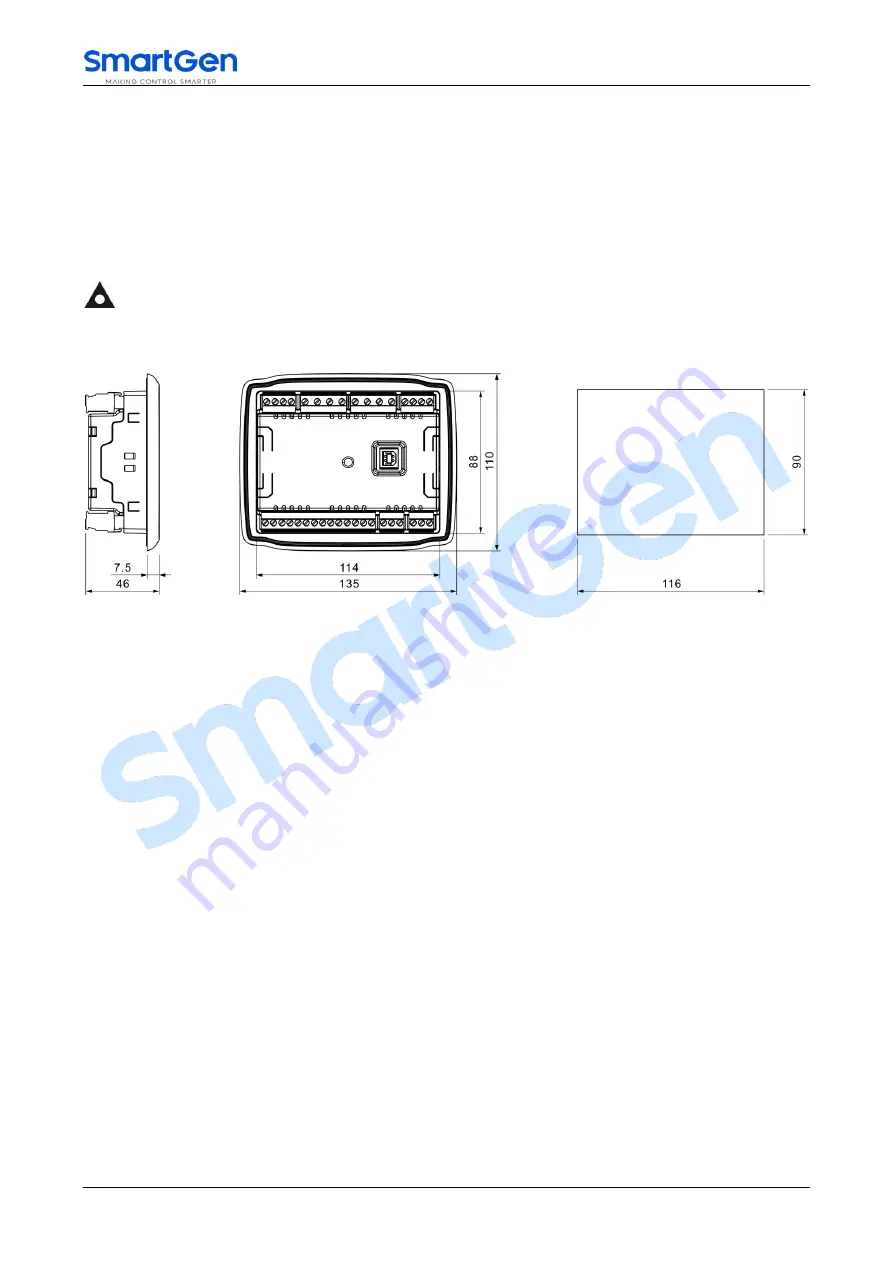
OVERALL DIMENSION AND CUTOUT
Fig.8
–
Overall Dimensions and Cutout (Unit: mm)
—
BATTERY VOLTAGE INPUT
HEM4000 controller is applicable to battery voltage DC (8~35)V environment. Negative anode of the
battery must be connected with the engine shell. Sectional area of the wire that connects with the
controller power B+ and B- must be equal to or over 1.5mm
2
. If floating charger is configured, please
connect output wires directly to the battery’s positive and negative anodes, and then connect wires from
battery’s positive and negative to the controller’s positive and negative input ends in order to prevent
charger disturbing the controller’s normal working.
—
SPEED SENSOR INPUT
Speed sensor is the magnetic equipment installed in the engine body to detect flywheel teeth number.
The wires used to connect with the controller shall be 2-core shielding wires. The shielding layer shall be
connected to No. 28 terminal on the controller, and meanwhile the other terminal shall be hanging in the air.
Another two signal wires shall be connected to No.28 and No.29 terminals on the controller. The output
voltage of the speed sensor shall be within AC (1~24)V (RMS) in the range of full speed and AC12V is
recommended (at rated speed). As to speed sensor installation, the sensor can firstly be spun to the
connection flywheel, then invert 1/3 lap, and finally tighten up the screw on the sensor.
—
OUTPUT AND EXPAND RELAYS
All controller outputs are relay contact outputs. If the expansion relay is needed, freewheel diode (relay
coil is DC) and resistor and capacitor circuit (relay coil is AC) shall be added to the two ends of the relay
coils in order to prevent disturbing the controller or others equipment.


